MicroMax's Solutions
MicroMax's Solutions
MicroMax's Solutions
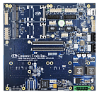
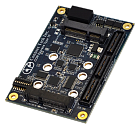 Carrier Board CCG030
COM Express Type 10 Stacking Carrier
Connect Tech’s COM Express Type 10 carrier, model CCG030, changes the design process completely! The CCG030 provides high density board to board connectors for use with either off-the-shelf or custom breakout boards, dramatically reducing the need for cabling.
With all of the complex circuitry already on the carrier, such as Gigabit Ethernet, USB 3.0, Serial, and Display, the design of a unique breakout board can be done with minimal effort and using Connect Tech’s design services or by the user.
CCG030 provides expansion via Mini-PCI Express which can be used for either Mini PCI Express peripherals or mSATA. In addition, both a SATA Link and a PCIe x1 Link with Clock are provided to the breakout board connector, allowing for breakout board expansion to meet your design needs.
Carrier Board CCG030
COM Express Type 10 Stacking Carrier
Connect Tech’s COM Express Type 10 carrier, model CCG030, changes the design process completely! The CCG030 provides high density board to board connectors for use with either off-the-shelf or custom breakout boards, dramatically reducing the need for cabling.
With all of the complex circuitry already on the carrier, such as Gigabit Ethernet, USB 3.0, Serial, and Display, the design of a unique breakout board can be done with minimal effort and using Connect Tech’s design services or by the user.
CCG030 provides expansion via Mini-PCI Express which can be used for either Mini PCI Express peripherals or mSATA. In addition, both a SATA Link and a PCIe x1 Link with Clock are provided to the breakout board connector, allowing for breakout board expansion to meet your design needs.
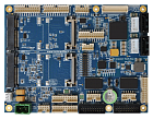
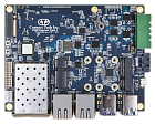 Carrier Board CCG070
COM Express Type 7 Carrier Board
Connect Tech’s COM Express Type 7 Carrier Board is based on the PICMG COM Express COM.0 R3.0 specification. It includes dual 10-Gigabit Ethernet from SFP+ modules, 2x GbE ports, M.2 NVMe Storage, 4x USB 3.0, full and half size Mini PCIe expansion slots, 8×3.3V buffered GPIO, and a Console connection via Micro USB.
The carrier board is ideal for high-compute, enterprise level applications that have a need for a small form factor rugged solution providing access to high-end Xeon D class processors.
Carrier Board CCG070
COM Express Type 7 Carrier Board
Connect Tech’s COM Express Type 7 Carrier Board is based on the PICMG COM Express COM.0 R3.0 specification. It includes dual 10-Gigabit Ethernet from SFP+ modules, 2x GbE ports, M.2 NVMe Storage, 4x USB 3.0, full and half size Mini PCIe expansion slots, 8×3.3V buffered GPIO, and a Console connection via Micro USB.
The carrier board is ideal for high-compute, enterprise level applications that have a need for a small form factor rugged solution providing access to high-end Xeon D class processors.
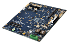
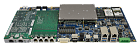
 Carrier Board CCG060
COM Express Type 6 Stacking Carrier
Connect Tech’s COM Express Type 6 carrier, model CCG060, changes the design process completely! The CCG060 provides high density board to board connectors for use with either off-the-shelf or custom breakout boards, dramatically reducing the need for cabling.
With all of the complex circuitry already on the carrier, such as Gigabit Ethernet, USB 3.0, Serial, and Display, the design of a unique breakout board can be done with minimal effort and using Connect Tech’s design services or by the user.
Use with off the shelf breakout boards, or easily design a custom breakout board to meet your needs. Access to the COM Express PCI Express x16 Bus enables high data throughout or bifurcation design options. In addition, both unused SATA Links and PCIe x1 Links with clocks are provided to the breakout board. All this allows for breakout board expansion to meet your design needs.
Carrier Board CCG060
COM Express Type 6 Stacking Carrier
Connect Tech’s COM Express Type 6 carrier, model CCG060, changes the design process completely! The CCG060 provides high density board to board connectors for use with either off-the-shelf or custom breakout boards, dramatically reducing the need for cabling.
With all of the complex circuitry already on the carrier, such as Gigabit Ethernet, USB 3.0, Serial, and Display, the design of a unique breakout board can be done with minimal effort and using Connect Tech’s design services or by the user.
Use with off the shelf breakout boards, or easily design a custom breakout board to meet your needs. Access to the COM Express PCI Express x16 Bus enables high data throughout or bifurcation design options. In addition, both unused SATA Links and PCIe x1 Links with clocks are provided to the breakout board. All this allows for breakout board expansion to meet your design needs.
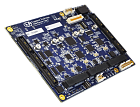
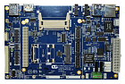
 Carrier Board CCG016
COM Express Type 6 PMC/XMC Lite Carrier
Connect Tech’s COM Express Type 6 PMC/XMC Lite Carrier Board is a compact, feature-rich carrier which offers dual PMC/XMC and Mini-PCIe expansion. This carrier board features USB 3.0 and DisplayPort, and supports the latest Intel processor sets.
The COM Express Type 6 PMC/ XMC Lite Carrier Board is ideal for military and aerospace applications, and accepts a wide input voltage range from a regulated or un-regulated source of +12V to +48V DC.
Carrier Board CCG016
COM Express Type 6 PMC/XMC Lite Carrier
Connect Tech’s COM Express Type 6 PMC/XMC Lite Carrier Board is a compact, feature-rich carrier which offers dual PMC/XMC and Mini-PCIe expansion. This carrier board features USB 3.0 and DisplayPort, and supports the latest Intel processor sets.
The COM Express Type 6 PMC/ XMC Lite Carrier Board is ideal for military and aerospace applications, and accepts a wide input voltage range from a regulated or un-regulated source of +12V to +48V DC.
 Carrier Board CCG013
COM Express Type 6 PMC/XMC Ultra Lite Carrier
Connect Tech’s COM Express Type 6 PMC/XMC Ultra Lite Carrier Board is a compact, feature-rich carrier which offers dual PMC/XMC and Mini-PCIe expansion. This carrier board features USB 3.0 and DisplayPort, and supports the latest Intel processor sets.
The COM Express Type 6 PMC/ XMC Ultra Lite Carrier Board is ideal for military and aerospace applications, and accepts a wide input voltage range from a regulated or un-regulated source of +12V to +48V DC.
Carrier Board CCG013
COM Express Type 6 PMC/XMC Ultra Lite Carrier
Connect Tech’s COM Express Type 6 PMC/XMC Ultra Lite Carrier Board is a compact, feature-rich carrier which offers dual PMC/XMC and Mini-PCIe expansion. This carrier board features USB 3.0 and DisplayPort, and supports the latest Intel processor sets.
The COM Express Type 6 PMC/ XMC Ultra Lite Carrier Board is ideal for military and aerospace applications, and accepts a wide input voltage range from a regulated or un-regulated source of +12V to +48V DC.
 Carrier Board CCG011/012
COM Express Type 6 Rugged Ultra Lite Carrier Board
Connect Tech’s COM Express Type 6 Rugged Ultra Lite Carrier Board is a compact carrier board which matches the dimensions of a COM Express Basic module and offers the ultimate durability with locking, rugged pin headers.
COM Express Type 6 Rugged Ultra Lite Carrier Board is ideal for space constrained applications, harsh environments, demanding conditions and supports extended temperature ranges of −40°C to +85°C.
Carrier Board CCG011/012
COM Express Type 6 Rugged Ultra Lite Carrier Board
Connect Tech’s COM Express Type 6 Rugged Ultra Lite Carrier Board is a compact carrier board which matches the dimensions of a COM Express Basic module and offers the ultimate durability with locking, rugged pin headers.
COM Express Type 6 Rugged Ultra Lite Carrier Board is ideal for space constrained applications, harsh environments, demanding conditions and supports extended temperature ranges of −40°C to +85°C.
 Carrier Board CCG007
COM Express Type 6 PMC/XMC Carrier Board
Connect Tech’s COM Express Type 6 PMC/XMC Carrier Board is a highly advanced, feature-rich carrier which offers PMC/XMC and Mini-PCIe expansion. This carrier board features USB 3.0 and DisplayPort, and supports the latest high performance Intel processors.
Carrier Board CCG007
COM Express Type 6 PMC/XMC Carrier Board
Connect Tech’s COM Express Type 6 PMC/XMC Carrier Board is a highly advanced, feature-rich carrier which offers PMC/XMC and Mini-PCIe expansion. This carrier board features USB 3.0 and DisplayPort, and supports the latest high performance Intel processors.
 Carrier Board CCG001/002/003
COM Express Type 2 Carrier Board
Connect Tech’s COM Express Carrier Board is a full‑featured, compact carrier board that is compatible with COM Express Type 2 Basic and Compact modules.
COM Express Carrier Board can be used as a stand-alone carrier board, or integrated directly into an existing application. It can also be used as a small evaluation platform for battery supported applications that use COM Express Compact modules.
COM Express Carrier Board is ideal for a host of embedded applications that require higher performance and I/O bandwidth in a compact form factor. System expansion capability and customization is available through application-specific carrier boards.
Carrier Board CCG001/002/003
COM Express Type 2 Carrier Board
Connect Tech’s COM Express Carrier Board is a full‑featured, compact carrier board that is compatible with COM Express Type 2 Basic and Compact modules.
COM Express Carrier Board can be used as a stand-alone carrier board, or integrated directly into an existing application. It can also be used as a small evaluation platform for battery supported applications that use COM Express Compact modules.
COM Express Carrier Board is ideal for a host of embedded applications that require higher performance and I/O bandwidth in a compact form factor. System expansion capability and customization is available through application-specific carrier boards.
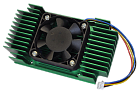 Active Heat Sink XHG302/XHG304
NVIDIA Jetson TX2, TX2 4GB, TX2i Active Heat Sink
Please Note: XHG302 supports TX2 only. For the NVIDIA Jetson TX2i and TX2 4GB, you will require the XHG304.
NVIDIA Jetson TX2 is a supercomputer on a module that’s the size of a credit card. Its performance, power efficiency, and technology make it ideal for embedded visual computing applications.
Connect Tech is proud to provide small form factor carriers and embedded system solutions for the TX2, TX2 4GB, or TX2i. To assist in your selection of their solutions, there are accessories to match the products. Readily available thermal options get you up and running fast.
Active Heat Sink XHG302/XHG304
NVIDIA Jetson TX2, TX2 4GB, TX2i Active Heat Sink
Please Note: XHG302 supports TX2 only. For the NVIDIA Jetson TX2i and TX2 4GB, you will require the XHG304.
NVIDIA Jetson TX2 is a supercomputer on a module that’s the size of a credit card. Its performance, power efficiency, and technology make it ideal for embedded visual computing applications.
Connect Tech is proud to provide small form factor carriers and embedded system solutions for the TX2, TX2 4GB, or TX2i. To assist in your selection of their solutions, there are accessories to match the products. Readily available thermal options get you up and running fast.
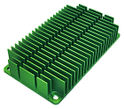 Passive Heat Sink XHG301/XHG303
NVIDIA Jetson TX2, TX2 4GB, TX2i Passive Heat Sink
Please Note: XHG301 supports TX2 only. For the NVIDIA Jetson TX2i and TX2 4GB, you will require the XHG303.
NVIDIA Jetson TX2 is a supercomputer on a module that’s the size of a credit card. Its performance, power efficiency, and technology make it ideal for embedded visual computing applications.
Connect Tech is proud to provide small form factor carriers and embedded system solutions for the TX2, TX2 4GB, or TX2i. To assist in your selection of their solutions, there are accessories to match the products. Readily available thermal options get you up and running fast.
Passive Heat Sink XHG301/XHG303
NVIDIA Jetson TX2, TX2 4GB, TX2i Passive Heat Sink
Please Note: XHG301 supports TX2 only. For the NVIDIA Jetson TX2i and TX2 4GB, you will require the XHG303.
NVIDIA Jetson TX2 is a supercomputer on a module that’s the size of a credit card. Its performance, power efficiency, and technology make it ideal for embedded visual computing applications.
Connect Tech is proud to provide small form factor carriers and embedded system solutions for the TX2, TX2 4GB, or TX2i. To assist in your selection of their solutions, there are accessories to match the products. Readily available thermal options get you up and running fast.
