MicroMax's Solutions
MicroMax's Solutions
MicroMax's Solutions
new
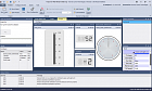 X-Analyser
Windows based tool to test your CAN, CAN FD, CANopen, J1939, NMEA2000, DeviceNet and LIN bus systems
X-Analyser Features
X-Analyser supports all of the typical features of a CAN, CAN FD, LIN analysis tool plus the following:
Simulate CAN, CAN FD & LIN Devices or Network — Message Builder for Transmission
You can build messages for transmission on a CAN, CAN FD or LIN bus from an .DBC or .LDF file. This saves time in converting decimal to hexadecimal and calculating scaling & offset. All you need to do is enter the signal physical value e.g. Engine Speed as 3000 rpm or Oil Temperature as degrees C.
CANopen
X-Analyser has support for the CANopen higher layer protocol which is used for industrial automation and other off-highway applications. There are two main areas of support for which you must have the X-Analyser Professional Edition; message/signal interpretation and transmission of Network Management messages to put individual nodes or the whole bus into different states.
NMEA 2000
The most powerful NMEA2000 test tool on the market. The NMEA2000 PGN signal database is embedded into X-Analyser which means that you can send or receive and interpret the data easily. The Fast Packet Protocol is supported for sending and receiving of NMEA2000 packets. CAN identifiers are interpreted as PGN, Source Address, Priority etc. and the data field is broken down into PGN fields and signals.
CAN Oscilloscope
X-Analyser captures CAN_H & CAN_L signals for each CAN frame on CAN bus
Can be used to carry out full CAN system audits
Help identify which ECUs or areas of CAN bus is experiencing electrical problems
Filter Editor
Use the filter editor to filter CAN frames on the Raw Data Trace they can be filtered by; Channel, Data, Data Length, Direction, Frame ID, Frame Type and Timestamp. These can be used with a combination of logic functions to define certain criteria for Filtering.
Gauges
With a CAN database loaded signals can be configured to show as gauges. With a combination of gauge styles available and gauge values can be defined such as; Min and Max values and Minor and Major Step Intervals.
Interactive Generator for CAN and J1939
The Interactive Generator (IG) allows the user to use a CANdb (*.dbc) file to interactively transmit CAN messages onto a system using the signals physical values that will automatically be converted to raw CAN data. Running in parallel with X-Analyser, the IG allows the user to create and change CAN messages on the fly. Transmission of a message can be carried out by user interaction (i.e. by clicking on a button) or by a timer with resolution 5ms which allows periodic transmitting.
ISO 15765 transmitter
Easily create a Mode 3 transmitter when the ISO 15765 Higher Layer Protocol has been added.
J1939 Signals Database
X-analyser Professional Edition comes with a J1939 database where signals can be selected and source address defined so they can be displayed in a Signals Panel, Gauge or Scope.
J1939 Signals
Within the J1939 Raw Trace tab available with X-analyser Professional CAN frames can be expanded to show the signals within that frame.
Object Transmitter
The Object Transmitter can be used to create CAN frames and transmit them onto a network. Standard and Extended ID’s can be selected, also Transmitters can be sent periodically by selecting Auto-Repeat and defining the time interval in milliseconds.
Graphing on Signals Scope
With a CAN, CAN FD or LIN database loaded, signals can be selected for the scope to displayed and plotted. Points on the scope can be selected to show the value at a certain time. The scope can also be exported to CSV format to be opened and worked with in Excel.
Signals Editor
The signals editor can be used to create parts of a CAN database on the fly, what’s created can be configure to a signals panel, gauges or scope.
Signals Panel
With a CAN database loaded signals can be configured to the signals panel to show physical values. The signals can be displayed numerically or symbolically.
Signals Search Function
CAN databases when loaded can be searched using the signals search function. Quotation marks can also be used to search for a whole name i.e. «Engine RPM».
Symbolic and Numeric Values
X-analyser can now have the same signals displayed more than once on a signals panel, gauge or scope. Within a signals panel the same signal can be displayed more than once with each as a symbolic or numeric value.
UDS DTC reader
X-analyser now has a UDS DTC reader, once configured in the transport protocol for the UDS DTC reader. It shall read and clear UDS DTC’s with the option to set the DTC Status Mask so different ECU’s can be read.
LIN Schedule Tables
When you load a LDF into X-Analyser, you can load the Schedule Table into the Object Transmitter to simulate all or some of the nodes on the LIN bus.
Supports industry standard log files and databases
X-Analyser uses industry standard files so that they can be easily shared between your engineers, customers and supplier. For description of Controller Area Networks (CAN), X-Analyser supports the CAN database file format (*.dbc). For description of Local Interconnect Networks (LIN), X-Analyser supports the LIN Description File (LDF) format (*.ldf). For logs of CAN data, X-Analyser supports log files in the ASCII file format (*.asc).
Virtual networks and channels for off-line analysis
A number of virtual buses are available with X-Analyser which are useful for off-line demonstration or working away with data captured from the CAN or LIN bus so that the data can be reviewed and played back on the PC without the need for a network interface. Virtual buses include:
Native virtual X-Analyser virtual buses that are connected in a simulated loop-back. This is ideal for play-back purposes.
Random CAN generator which generates a CAN message of ID 0×500 with a data field that contains a sine wave and a number of random signal waveforms.
Random LIN generator which generates a LIN message of ID 0×32 with a data field that contains a sine wave and a number of random signal waveforms.
Random CAN-FD generator which generates a CAN message of ID 0×500, DLC 48 with a data field that contains a sine wave and a number of random signal waveforms.
In addition to this if you are using a Kvaser or Vector interface then you can use the virtual channels that are provided by these manufacturers.
Easy Project Sharing
X-Analyser’s project files means that you can put together different setups and GUI displays for different projects, vehicles and networks.
Embedding of CAN or LIN databases into the X-Analyser projects mean easy sharing of project files without having to worry about the database linking or location.
X-Analyser
Windows based tool to test your CAN, CAN FD, CANopen, J1939, NMEA2000, DeviceNet and LIN bus systems
X-Analyser Features
X-Analyser supports all of the typical features of a CAN, CAN FD, LIN analysis tool plus the following:
Simulate CAN, CAN FD & LIN Devices or Network — Message Builder for Transmission
You can build messages for transmission on a CAN, CAN FD or LIN bus from an .DBC or .LDF file. This saves time in converting decimal to hexadecimal and calculating scaling & offset. All you need to do is enter the signal physical value e.g. Engine Speed as 3000 rpm or Oil Temperature as degrees C.
CANopen
X-Analyser has support for the CANopen higher layer protocol which is used for industrial automation and other off-highway applications. There are two main areas of support for which you must have the X-Analyser Professional Edition; message/signal interpretation and transmission of Network Management messages to put individual nodes or the whole bus into different states.
NMEA 2000
The most powerful NMEA2000 test tool on the market. The NMEA2000 PGN signal database is embedded into X-Analyser which means that you can send or receive and interpret the data easily. The Fast Packet Protocol is supported for sending and receiving of NMEA2000 packets. CAN identifiers are interpreted as PGN, Source Address, Priority etc. and the data field is broken down into PGN fields and signals.
CAN Oscilloscope
X-Analyser captures CAN_H & CAN_L signals for each CAN frame on CAN bus
Can be used to carry out full CAN system audits
Help identify which ECUs or areas of CAN bus is experiencing electrical problems
Filter Editor
Use the filter editor to filter CAN frames on the Raw Data Trace they can be filtered by; Channel, Data, Data Length, Direction, Frame ID, Frame Type and Timestamp. These can be used with a combination of logic functions to define certain criteria for Filtering.
Gauges
With a CAN database loaded signals can be configured to show as gauges. With a combination of gauge styles available and gauge values can be defined such as; Min and Max values and Minor and Major Step Intervals.
Interactive Generator for CAN and J1939
The Interactive Generator (IG) allows the user to use a CANdb (*.dbc) file to interactively transmit CAN messages onto a system using the signals physical values that will automatically be converted to raw CAN data. Running in parallel with X-Analyser, the IG allows the user to create and change CAN messages on the fly. Transmission of a message can be carried out by user interaction (i.e. by clicking on a button) or by a timer with resolution 5ms which allows periodic transmitting.
ISO 15765 transmitter
Easily create a Mode 3 transmitter when the ISO 15765 Higher Layer Protocol has been added.
J1939 Signals Database
X-analyser Professional Edition comes with a J1939 database where signals can be selected and source address defined so they can be displayed in a Signals Panel, Gauge or Scope.
J1939 Signals
Within the J1939 Raw Trace tab available with X-analyser Professional CAN frames can be expanded to show the signals within that frame.
Object Transmitter
The Object Transmitter can be used to create CAN frames and transmit them onto a network. Standard and Extended ID’s can be selected, also Transmitters can be sent periodically by selecting Auto-Repeat and defining the time interval in milliseconds.
Graphing on Signals Scope
With a CAN, CAN FD or LIN database loaded, signals can be selected for the scope to displayed and plotted. Points on the scope can be selected to show the value at a certain time. The scope can also be exported to CSV format to be opened and worked with in Excel.
Signals Editor
The signals editor can be used to create parts of a CAN database on the fly, what’s created can be configure to a signals panel, gauges or scope.
Signals Panel
With a CAN database loaded signals can be configured to the signals panel to show physical values. The signals can be displayed numerically or symbolically.
Signals Search Function
CAN databases when loaded can be searched using the signals search function. Quotation marks can also be used to search for a whole name i.e. «Engine RPM».
Symbolic and Numeric Values
X-analyser can now have the same signals displayed more than once on a signals panel, gauge or scope. Within a signals panel the same signal can be displayed more than once with each as a symbolic or numeric value.
UDS DTC reader
X-analyser now has a UDS DTC reader, once configured in the transport protocol for the UDS DTC reader. It shall read and clear UDS DTC’s with the option to set the DTC Status Mask so different ECU’s can be read.
LIN Schedule Tables
When you load a LDF into X-Analyser, you can load the Schedule Table into the Object Transmitter to simulate all or some of the nodes on the LIN bus.
Supports industry standard log files and databases
X-Analyser uses industry standard files so that they can be easily shared between your engineers, customers and supplier. For description of Controller Area Networks (CAN), X-Analyser supports the CAN database file format (*.dbc). For description of Local Interconnect Networks (LIN), X-Analyser supports the LIN Description File (LDF) format (*.ldf). For logs of CAN data, X-Analyser supports log files in the ASCII file format (*.asc).
Virtual networks and channels for off-line analysis
A number of virtual buses are available with X-Analyser which are useful for off-line demonstration or working away with data captured from the CAN or LIN bus so that the data can be reviewed and played back on the PC without the need for a network interface. Virtual buses include:
Native virtual X-Analyser virtual buses that are connected in a simulated loop-back. This is ideal for play-back purposes.
Random CAN generator which generates a CAN message of ID 0×500 with a data field that contains a sine wave and a number of random signal waveforms.
Random LIN generator which generates a LIN message of ID 0×32 with a data field that contains a sine wave and a number of random signal waveforms.
Random CAN-FD generator which generates a CAN message of ID 0×500, DLC 48 with a data field that contains a sine wave and a number of random signal waveforms.
In addition to this if you are using a Kvaser or Vector interface then you can use the virtual channels that are provided by these manufacturers.
Easy Project Sharing
X-Analyser’s project files means that you can put together different setups and GUI displays for different projects, vehicles and networks.
Embedding of CAN or LIN databases into the X-Analyser projects mean easy sharing of project files without having to worry about the database linking or location.
 M-Max HR 3U
Rugged 19/2” Conduction-Cooled Systems Family
The M-Max® HR 3U rugged industrial system provides reliable operation in tough environments.
The fully-ruggedized 19/2"-type aluminum chassis is fanless and uses natural convection and conduction cooling to comply with MIL-STD-810 standards. Versatile mechanical design of the enclosure allows to combine several systems into one assembly side by side or by stacking, mount them on a flat surface or into a 19″ rack using appropriate mounting parts. COTS technology components allow configuring the system to comply with a wide variety of airborne, marine and ground vehicle applications.
The M-Max® HR 3U system is compatible with the following M-Max® platforms: GX Platform, PR7 Platform, AR Platform, DT Platform, EP4 Platform, CU Platform.
M-Max HR 3U
Rugged 19/2” Conduction-Cooled Systems Family
The M-Max® HR 3U rugged industrial system provides reliable operation in tough environments.
The fully-ruggedized 19/2"-type aluminum chassis is fanless and uses natural convection and conduction cooling to comply with MIL-STD-810 standards. Versatile mechanical design of the enclosure allows to combine several systems into one assembly side by side or by stacking, mount them on a flat surface or into a 19″ rack using appropriate mounting parts. COTS technology components allow configuring the system to comply with a wide variety of airborne, marine and ground vehicle applications.
The M-Max® HR 3U system is compatible with the following M-Max® platforms: GX Platform, PR7 Platform, AR Platform, DT Platform, EP4 Platform, CU Platform.
X-Analyser
Windows based tool to test your CAN, CAN FD, CANopen, J1939, NMEA2000, DeviceNet and LIN bus systems
X-Analyser Features
X-Analyser supports all of the typical features of a CAN, CAN FD, LIN analysis tool plus the following:
Simulate CAN, CAN FD & LIN Devices or Network — Message Builder for Transmission
You can build messages for transmission on a CAN, CAN FD or LIN bus from an .DBC or .LDF file. This saves time in converting decimal to hexadecimal and calculating scaling & offset. All you need to do is enter the signal physical value e.g. Engine Speed as 3000 rpm or Oil Temperature as degrees C.
CANopen
X-Analyser has support for the CANopen higher layer protocol which is used for industrial automation and other off-highway applications. There are two main areas of support for which you must have the X-Analyser Professional Edition; message/signal interpretation and transmission of Network Management messages to put individual nodes or the whole bus into different states.
NMEA 2000
The most powerful NMEA2000 test tool on the market. The NMEA2000 PGN signal database is embedded into X-Analyser which means that you can send or receive and interpret the data easily. The Fast Packet Protocol is supported for sending and receiving of NMEA2000 packets. CAN identifiers are interpreted as PGN, Source Address, Priority etc. and the data field is broken down into PGN fields and signals.
CAN Oscilloscope
X-Analyser captures CAN_H & CAN_L signals for each CAN frame on CAN bus
Can be used to carry out full CAN system audits
Help identify which ECUs or areas of CAN bus is experiencing electrical problems
Filter Editor
Use the filter editor to filter CAN frames on the Raw Data Trace they can be filtered by; Channel, Data, Data Length, Direction, Frame ID, Frame Type and Timestamp. These can be used with a combination of logic functions to define certain criteria for Filtering.
Gauges
With a CAN database loaded signals can be configured to show as gauges. With a combination of gauge styles available and gauge values can be defined such as; Min and Max values and Minor and Major Step Intervals.
Interactive Generator for CAN and J1939
The Interactive Generator (IG) allows the user to use a CANdb (*.dbc) file to interactively transmit CAN messages onto a system using the signals physical values that will automatically be converted to raw CAN data. Running in parallel with X-Analyser, the IG allows the user to create and change CAN messages on the fly. Transmission of a message can be carried out by user interaction (i.e. by clicking on a button) or by a timer with resolution 5ms which allows periodic transmitting.
ISO 15765 transmitter
Easily create a Mode 3 transmitter when the ISO 15765 Higher Layer Protocol has been added.
J1939 Signals Database
X-analyser Professional Edition comes with a J1939 database where signals can be selected and source address defined so they can be displayed in a Signals Panel, Gauge or Scope.
J1939 Signals
Within the J1939 Raw Trace tab available with X-analyser Professional CAN frames can be expanded to show the signals within that frame.
Object Transmitter
The Object Transmitter can be used to create CAN frames and transmit them onto a network. Standard and Extended ID’s can be selected, also Transmitters can be sent periodically by selecting Auto-Repeat and defining the time interval in milliseconds.
Graphing on Signals Scope
With a CAN, CAN FD or LIN database loaded, signals can be selected for the scope to displayed and plotted. Points on the scope can be selected to show the value at a certain time. The scope can also be exported to CSV format to be opened and worked with in Excel.
Signals Editor
The signals editor can be used to create parts of a CAN database on the fly, what’s created can be configure to a signals panel, gauges or scope.
Signals Panel
With a CAN database loaded signals can be configured to the signals panel to show physical values. The signals can be displayed numerically or symbolically.
Signals Search Function
CAN databases when loaded can be searched using the signals search function. Quotation marks can also be used to search for a whole name i.e. «Engine RPM».
Symbolic and Numeric Values
X-analyser can now have the same signals displayed more than once on a signals panel, gauge or scope. Within a signals panel the same signal can be displayed more than once with each as a symbolic or numeric value.
UDS DTC reader
X-analyser now has a UDS DTC reader, once configured in the transport protocol for the UDS DTC reader. It shall read and clear UDS DTC’s with the option to set the DTC Status Mask so different ECU’s can be read.
LIN Schedule Tables
When you load a LDF into X-Analyser, you can load the Schedule Table into the Object Transmitter to simulate all or some of the nodes on the LIN bus.
Supports industry standard log files and databases
X-Analyser uses industry standard files so that they can be easily shared between your engineers, customers and supplier. For description of Controller Area Networks (CAN), X-Analyser supports the CAN database file format (*.dbc). For description of Local Interconnect Networks (LIN), X-Analyser supports the LIN Description File (LDF) format (*.ldf). For logs of CAN data, X-Analyser supports log files in the ASCII file format (*.asc).
Virtual networks and channels for off-line analysis
A number of virtual buses are available with X-Analyser which are useful for off-line demonstration or working away with data captured from the CAN or LIN bus so that the data can be reviewed and played back on the PC without the need for a network interface. Virtual buses include:
Native virtual X-Analyser virtual buses that are connected in a simulated loop-back. This is ideal for play-back purposes.
Random CAN generator which generates a CAN message of ID 0×500 with a data field that contains a sine wave and a number of random signal waveforms.
Random LIN generator which generates a LIN message of ID 0×32 with a data field that contains a sine wave and a number of random signal waveforms.
Random CAN-FD generator which generates a CAN message of ID 0×500, DLC 48 with a data field that contains a sine wave and a number of random signal waveforms.
In addition to this if you are using a Kvaser or Vector interface then you can use the virtual channels that are provided by these manufacturers.
Easy Project Sharing
X-Analyser’s project files means that you can put together different setups and GUI displays for different projects, vehicles and networks.
Embedding of CAN or LIN databases into the X-Analyser projects mean easy sharing of project files without having to worry about the database linking or location.
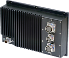
M-Max HR 3U
Rugged 19/2” Conduction-Cooled Systems Family
The M-Max® HR 3U rugged industrial system provides reliable operation in tough environments.
The fully-ruggedized 19/2"-type aluminum chassis is fanless and uses natural convection and conduction cooling to comply with MIL-STD-810 standards. Versatile mechanical design of the enclosure allows to combine several systems into one assembly side by side or by stacking, mount them on a flat surface or into a 19″ rack using appropriate mounting parts. COTS technology components allow configuring the system to comply with a wide variety of airborne, marine and ground vehicle applications.
The M-Max® HR 3U system is compatible with the following M-Max® platforms: GX Platform, PR7 Platform, AR Platform, DT Platform, EP4 Platform, CU Platform.
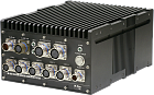
 M-Max ATR
Rugged ATR Conduction-Cooled Systems Family
The M-Max® ATR is an ATR-compliant family of fully sealed rugged systems with passive cooling, providing extreme physical protection for high performance applications.
The machine-worked aluminum chassis is especially designed for the most challenging environments. Providing excellent shock and vibration protection, the completely fanless chassis uses natural convection and conduction cooling.
The fully sealed 1/2 ATR Short version enclosure houses up to 8 PC/104 or similar-sized boards. The configurable front panel can be outfitted with a variety of customer-defined connectors.
The M-Max® ATR system is compatible with the following M-Max® platforms: PR7 Platform, AR Platform, DT Platform, EP4 Platform, CU Platform.
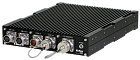
M-Max ATR
Rugged ATR Conduction-Cooled Systems Family
The M-Max® ATR is an ATR-compliant family of fully sealed rugged systems with passive cooling, providing extreme physical protection for high performance applications.
The machine-worked aluminum chassis is especially designed for the most challenging environments. Providing excellent shock and vibration protection, the completely fanless chassis uses natural convection and conduction cooling.
The fully sealed 1/2 ATR Short version enclosure houses up to 8 PC/104 or similar-sized boards. The configurable front panel can be outfitted with a variety of customer-defined connectors.
The M-Max® ATR system is compatible with the following M-Max® platforms: PR7 Platform, AR Platform, DT Platform, EP4 Platform, CU Platform.
 M-Max PD 7
Rugged Pandora-based Conduction-Cooled Systems Family
The M-Max® PD 7 is a compact lightweight rugged system in which the number of internal cables is reduced to the minimum. The use of this approach considerably speeds up the assembly process and improves reliability and ruggedness because most or all internal cables can be eliminated.
The entire stack doesn’t require any special corner mounts or guides and is bolted directly to the front plate of the case, forming a rugged, easily-handled assembly.
One end cap of the M-Max® PD 7 system serves as a base plate for the PC/104 stack with the panel I/O board on the top of the stack. Once the stack is complete, it is inserted into the enclosure and bolted into place directly to both the top and the bottom of the enclosure via convenient mounting holes for extra rigidity.
The M-Max® PD 7 system is compatible with PR7 Platform
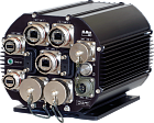
M-Max PD 7
Rugged Pandora-based Conduction-Cooled Systems Family
The M-Max® PD 7 is a compact lightweight rugged system in which the number of internal cables is reduced to the minimum. The use of this approach considerably speeds up the assembly process and improves reliability and ruggedness because most or all internal cables can be eliminated.
The entire stack doesn’t require any special corner mounts or guides and is bolted directly to the front plate of the case, forming a rugged, easily-handled assembly.
One end cap of the M-Max® PD 7 system serves as a base plate for the PC/104 stack with the panel I/O board on the top of the stack. Once the stack is complete, it is inserted into the enclosure and bolted into place directly to both the top and the bottom of the enclosure via convenient mounting holes for extra rigidity.
The M-Max® PD 7 system is compatible with PR7 Platform
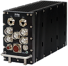
 M-Max VI
Rugged VITA 75-Compliant Conduction-Cooled Systems Family
The M-Max® VI system, designed according to the VITA 75 footprint, is a fully sealed rugged system with passive cooling, providing reliable operation in tough environments including transportation (ground, rail, air and marine), agriculture, mining and processing. Its machine-worked aluminum chassis is especially designed for the most challenging environments.
Providing excellent shock and vibration protection, the completely fanless M-Max® VI uses natural convection and conduction cooling and is able to deliver IP66 dust and moisture protection, withstand shocks up to 40g and vibration up to 2.5g.
The system has two enclosure options to better suit your space requirements — full and short version. The VITA 75-compliant M-Max® VI system is tested and guaranteed over temperature range of -40 to +70°C. The embedded power supply (in full version) complies with MIL-STD-704F specification.
The M-Max® VI system is compatible with the following M-Max® platforms: PR7 Platform, EP4 Platform (Quad Core i5-6442EQ only).
M-Max VI
Rugged VITA 75-Compliant Conduction-Cooled Systems Family
The M-Max® VI system, designed according to the VITA 75 footprint, is a fully sealed rugged system with passive cooling, providing reliable operation in tough environments including transportation (ground, rail, air and marine), agriculture, mining and processing. Its machine-worked aluminum chassis is especially designed for the most challenging environments.
Providing excellent shock and vibration protection, the completely fanless M-Max® VI uses natural convection and conduction cooling and is able to deliver IP66 dust and moisture protection, withstand shocks up to 40g and vibration up to 2.5g.
The system has two enclosure options to better suit your space requirements — full and short version. The VITA 75-compliant M-Max® VI system is tested and guaranteed over temperature range of -40 to +70°C. The embedded power supply (in full version) complies with MIL-STD-704F specification.
The M-Max® VI system is compatible with the following M-Max® platforms: PR7 Platform, EP4 Platform (Quad Core i5-6442EQ only).
 M-Max HR 1U
Rugged 19/2” Conduction-Cooled Systems Family
The M-Max® HR 1U rugged industrial system provides reliable operation in tough environments.
The fully-ruggedized 19/2"-type aluminum chassis is fanless and uses natural convection and conduction cooling to comply with MIL-STD-810 standards. Versatile mechanical design of the enclosure allows to combine several systems into one assembly side by side or by stacking, mount them on a flat surface or into a 19″ rack using appropriate mounting parts. COTS technology components allow configuring the system to comply with a wide variety of airborne, marine and ground vehicle applications.
The M-Max® HR 1U system is compatible with the following M-Max® platforms: LP Platform, GX Platform, PR7 Platform, DT Platform.
M-Max HR 1U
Rugged 19/2” Conduction-Cooled Systems Family
The M-Max® HR 1U rugged industrial system provides reliable operation in tough environments.
The fully-ruggedized 19/2"-type aluminum chassis is fanless and uses natural convection and conduction cooling to comply with MIL-STD-810 standards. Versatile mechanical design of the enclosure allows to combine several systems into one assembly side by side or by stacking, mount them on a flat surface or into a 19″ rack using appropriate mounting parts. COTS technology components allow configuring the system to comply with a wide variety of airborne, marine and ground vehicle applications.
The M-Max® HR 1U system is compatible with the following M-Max® platforms: LP Platform, GX Platform, PR7 Platform, DT Platform.
 M-Max VT
Rugged VersaTainer-based Conduction-Cooled Systems Family
The M-Max® VT is a rugged EBX and PC/104 system designed mostly for on-board applications. It is constructed of .125″ aluminum and is ready to be used in harsh environments.
It features a dual system of shock and vibration protection comprised of internal rubber corner rails which absorb high-frequency vibrations, while a thick rubber pad between the enclosure and the host platform absorbs low-frequency G-forces. The rubber pad may be removed for other mounting solutions. The M-Max® VT cross section measures 7.10″ wide by 5.70″ high (not including mounting pad). The system is available in standard lengths from 4″ to 12″ and custom lengths up to 48″.
The M-Max® VT can be used in the harshest environments in the mining, transportation, military, and aerospace industries. The system and its standard accessories are RoHS compliant.
The M-Max® VT system is compatible with the following M-Max® platforms: PR7 Platform, AR Platform.
M-Max VT
Rugged VersaTainer-based Conduction-Cooled Systems Family
The M-Max® VT is a rugged EBX and PC/104 system designed mostly for on-board applications. It is constructed of .125″ aluminum and is ready to be used in harsh environments.
It features a dual system of shock and vibration protection comprised of internal rubber corner rails which absorb high-frequency vibrations, while a thick rubber pad between the enclosure and the host platform absorbs low-frequency G-forces. The rubber pad may be removed for other mounting solutions. The M-Max® VT cross section measures 7.10″ wide by 5.70″ high (not including mounting pad). The system is available in standard lengths from 4″ to 12″ and custom lengths up to 48″.
The M-Max® VT can be used in the harshest environments in the mining, transportation, military, and aerospace industries. The system and its standard accessories are RoHS compliant.
The M-Max® VT system is compatible with the following M-Max® platforms: PR7 Platform, AR Platform.
 M-Max PD 2
Rugged Pandora-based Conduction-Cooled Systems Family
The M-Max® PD 2 is a compact lightweight rugged system in which the number of internal cables is reduced to the minimum. The use of this approach considerably speeds up the assembly process and improves reliability and ruggedness because most or all internal cables can be eliminated.
The entire stack doesn’t require any special corner mounts or guides and is bolted directly to the front plate of the case, forming a rugged, easily-handled assembly.
One end cap of the M-Max® PD 2 system serves as a base plate for the PC/104 stack with the panel I/O board on the top of the stack. Once the stack is complete, it is inserted into the enclosure and bolted into place directly to both the top and the bottom of the enclosure via convenient mounting holes for extra rigidity.
The M-Max® PD 2 system is compatible with the LP Platform.
M-Max PD 2
Rugged Pandora-based Conduction-Cooled Systems Family
The M-Max® PD 2 is a compact lightweight rugged system in which the number of internal cables is reduced to the minimum. The use of this approach considerably speeds up the assembly process and improves reliability and ruggedness because most or all internal cables can be eliminated.
The entire stack doesn’t require any special corner mounts or guides and is bolted directly to the front plate of the case, forming a rugged, easily-handled assembly.
One end cap of the M-Max® PD 2 system serves as a base plate for the PC/104 stack with the panel I/O board on the top of the stack. Once the stack is complete, it is inserted into the enclosure and bolted into place directly to both the top and the bottom of the enclosure via convenient mounting holes for extra rigidity.
The M-Max® PD 2 system is compatible with the LP Platform.
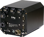
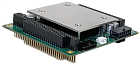 MM-PSF
Isolated PC/104 Power Supplies
The MM-PSF is an embedded isolated power supply by MicroMax Computer Intelligence, designed specifically for РС/104 systems.
It provides a РС/104 system with 12V DC (5A max.), 5V DC (12A max.), 3.3V DC (2.5A or 7A max.), −12V DC (2A max.) output voltages. The combined power of the device is up to 60W.
The power supply features reverse polarity protection and transient voltage surge suppression. The MM-PSF has advanced electromagnetic compatibility (MIL-STD-461F compliant).
The output power is supplied to latching connectors, as well as to system buses PCI-104 and PC/104. The device features short circuit protection with no time limit. As soon as the connection is recovered, the MM-PSF restores power supply automatically.
The MM-PSF is designed in compliance with vehicle standards MIL-STD-1275D and MIL-STD-704F.
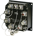
MM-PSF
Isolated PC/104 Power Supplies
The MM-PSF is an embedded isolated power supply by MicroMax Computer Intelligence, designed specifically for РС/104 systems.
It provides a РС/104 system with 12V DC (5A max.), 5V DC (12A max.), 3.3V DC (2.5A or 7A max.), −12V DC (2A max.) output voltages. The combined power of the device is up to 60W.
The power supply features reverse polarity protection and transient voltage surge suppression. The MM-PSF has advanced electromagnetic compatibility (MIL-STD-461F compliant).
The output power is supplied to latching connectors, as well as to system buses PCI-104 and PC/104. The device features short circuit protection with no time limit. As soon as the connection is recovered, the MM-PSF restores power supply automatically.
The MM-PSF is designed in compliance with vehicle standards MIL-STD-1275D and MIL-STD-704F.
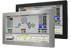 MM Monitors
12" to 23" Panel/Universal Mount Industrial Monitors and Touch Screens
MicroMax’ panel mount and universal mount industrial monitors are designed to provide the industrial user with excellent picture quality and rugged design for reliable continuous operation.
A unique single-cutout, stud-free design and depths of only 1.82″ to 2.12″ make panel mount monitors a snap to install. Options like touch screens and KVM Extenders make these displays highly versatile.
Universal mount monitors are extremely versatile and can be mounted to the floor on a pedestal, attached to a wall, column, or post, or even hung from the ceiling; anywhere in the factory a display or touch screen is needed.
Power input of the monitors is either 100 to 240 VAC, 1.5/0.75 A, 60/50 Hz or 9.6 to 36.6 VDC, 2.5 to 0.65 A
MM Monitors
12" to 23" Panel/Universal Mount Industrial Monitors and Touch Screens
MicroMax’ panel mount and universal mount industrial monitors are designed to provide the industrial user with excellent picture quality and rugged design for reliable continuous operation.
A unique single-cutout, stud-free design and depths of only 1.82″ to 2.12″ make panel mount monitors a snap to install. Options like touch screens and KVM Extenders make these displays highly versatile.
Universal mount monitors are extremely versatile and can be mounted to the floor on a pedestal, attached to a wall, column, or post, or even hung from the ceiling; anywhere in the factory a display or touch screen is needed.
Power input of the monitors is either 100 to 240 VAC, 1.5/0.75 A, 60/50 Hz or 9.6 to 36.6 VDC, 2.5 to 0.65 A
