MicroMax's Solutions
MicroMax's Solutions
MicroMax's Solutions
new
 CloudCommander
All-in-One CAN to Cloud datalogging solution
ODOSOLUTIONS AB (ODOS) and Kvaser AB have brought together a fresh perspective, unique collaboration, and advanced technology, in order to deliver next generation cloud connectivity and data logging for CAN (controller area network).
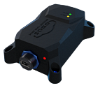
ODOS’ CloudCommander is a 4G-enabled data logger that integrates Kvaser’s well-known CAN interface hardware. ODOS’ Cloudsoft software platform, plus dashboard makes this a comprehensive CAN-to-Cloud data logging solution.
CloudCommander Features
The CloudCommander data logger combines the scale of Kvaser’s most popular CAN interface — the Kvaser Leaf Light — with the power of ODOS’ industry leading IoT Cloud Platform, to bring you a comprehensive CAN-to-Cloud datalogging solution:
Real-time CAN data streaming over 4G cellular connectivity to Cloud data storage
GPS tracking and 3-axis Accelerometer
Onboard UPS and memory buffer in the event of power and cellular connectivity outages
Native Kvaser Leaf (CANlib SDK) Interface and API
Rugged waterproof (IP67) field deployable enclosure with secure mounting location
CloudSoft Features
The tight vertical integration with award-winning CloudSoft platform and dashboard offers:
Remote real-time CAN data monitoring and analysis software
Over-The-Air (OTA) data-logger configuration updates
OTA Diagnostic Protocols on CAN (OBD2 & UDS)
Event based triggering to stream data, capture CAN traces and email alerts/reports
Virtual calculated CAN channels
Distributed team collaboration and data sharing platform
Plugins and REST API service
ASAM file formats
Certified to the most rigorous IT security and privacy (GDPR) legislation
What’s more, the CloudCommander incorporates a Kvaser USB-CAN interface to support your existing PC Applications whilst simultaneously streaming data to the cloud for remote fleet monitoring and diagnostics support.
new
CloudCommander
All-in-One CAN to Cloud datalogging solution
ODOSOLUTIONS AB (ODOS) and Kvaser AB have brought together a fresh perspective, unique collaboration, and advanced technology, in order to deliver next generation cloud connectivity and data logging for CAN (controller area network).
ODOS’ CloudCommander is a 4G-enabled data logger that integrates Kvaser’s well-known CAN interface hardware. ODOS’ Cloudsoft software platform, plus dashboard makes this a comprehensive CAN-to-Cloud data logging solution.
CloudCommander Features
The CloudCommander data logger combines the scale of Kvaser’s most popular CAN interface — the Kvaser Leaf Light — with the power of ODOS’ industry leading IoT Cloud Platform, to bring you a comprehensive CAN-to-Cloud datalogging solution:
Real-time CAN data streaming over 4G cellular connectivity to Cloud data storage
GPS tracking and 3-axis Accelerometer
Onboard UPS and memory buffer in the event of power and cellular connectivity outages
Native Kvaser Leaf (CANlib SDK) Interface and API
Rugged waterproof (IP67) field deployable enclosure with secure mounting location
CloudSoft Features
The tight vertical integration with award-winning CloudSoft platform and dashboard offers:
Remote real-time CAN data monitoring and analysis software
Over-The-Air (OTA) data-logger configuration updates
OTA Diagnostic Protocols on CAN (OBD2 & UDS)
Event based triggering to stream data, capture CAN traces and email alerts/reports
Virtual calculated CAN channels
Distributed team collaboration and data sharing platform
Plugins and REST API service
ASAM file formats
Certified to the most rigorous IT security and privacy (GDPR) legislation
What’s more, the CloudCommander incorporates a Kvaser USB-CAN interface to support your existing PC Applications whilst simultaneously streaming data to the cloud for remote fleet monitoring and diagnostics support.
new
 X-Analyser
Windows based tool to test your CAN, CAN FD, CANopen, J1939, NMEA2000, DeviceNet and LIN bus systems
X-Analyser Features
X-Analyser supports all of the typical features of a CAN, CAN FD, LIN analysis tool plus the following:
Simulate CAN, CAN FD & LIN Devices or Network — Message Builder for Transmission
You can build messages for transmission on a CAN, CAN FD or LIN bus from an .DBC or .LDF file. This saves time in converting decimal to hexadecimal and calculating scaling & offset. All you need to do is enter the signal physical value e.g. Engine Speed as 3000 rpm or Oil Temperature as degrees C.
CANopen
X-Analyser has support for the CANopen higher layer protocol which is used for industrial automation and other off-highway applications. There are two main areas of support for which you must have the X-Analyser Professional Edition; message/signal interpretation and transmission of Network Management messages to put individual nodes or the whole bus into different states.
NMEA 2000
The most powerful NMEA2000 test tool on the market. The NMEA2000 PGN signal database is embedded into X-Analyser which means that you can send or receive and interpret the data easily. The Fast Packet Protocol is supported for sending and receiving of NMEA2000 packets. CAN identifiers are interpreted as PGN, Source Address, Priority etc. and the data field is broken down into PGN fields and signals.
CAN Oscilloscope
X-Analyser captures CAN_H & CAN_L signals for each CAN frame on CAN bus
Can be used to carry out full CAN system audits
Help identify which ECUs or areas of CAN bus is experiencing electrical problems
Filter Editor
Use the filter editor to filter CAN frames on the Raw Data Trace they can be filtered by; Channel, Data, Data Length, Direction, Frame ID, Frame Type and Timestamp. These can be used with a combination of logic functions to define certain criteria for Filtering.
Gauges
With a CAN database loaded signals can be configured to show as gauges. With a combination of gauge styles available and gauge values can be defined such as; Min and Max values and Minor and Major Step Intervals.
Interactive Generator for CAN and J1939
The Interactive Generator (IG) allows the user to use a CANdb (*.dbc) file to interactively transmit CAN messages onto a system using the signals physical values that will automatically be converted to raw CAN data. Running in parallel with X-Analyser, the IG allows the user to create and change CAN messages on the fly. Transmission of a message can be carried out by user interaction (i.e. by clicking on a button) or by a timer with resolution 5ms which allows periodic transmitting.
ISO 15765 transmitter
Easily create a Mode 3 transmitter when the ISO 15765 Higher Layer Protocol has been added.
J1939 Signals Database
X-analyser Professional Edition comes with a J1939 database where signals can be selected and source address defined so they can be displayed in a Signals Panel, Gauge or Scope.
J1939 Signals
Within the J1939 Raw Trace tab available with X-analyser Professional CAN frames can be expanded to show the signals within that frame.
Object Transmitter
The Object Transmitter can be used to create CAN frames and transmit them onto a network. Standard and Extended ID’s can be selected, also Transmitters can be sent periodically by selecting Auto-Repeat and defining the time interval in milliseconds.
Graphing on Signals Scope
With a CAN, CAN FD or LIN database loaded, signals can be selected for the scope to displayed and plotted. Points on the scope can be selected to show the value at a certain time. The scope can also be exported to CSV format to be opened and worked with in Excel.
Signals Editor
The signals editor can be used to create parts of a CAN database on the fly, what’s created can be configure to a signals panel, gauges or scope.
Signals Panel
With a CAN database loaded signals can be configured to the signals panel to show physical values. The signals can be displayed numerically or symbolically.
Signals Search Function
CAN databases when loaded can be searched using the signals search function. Quotation marks can also be used to search for a whole name i.e. «Engine RPM».
Symbolic and Numeric Values
X-analyser can now have the same signals displayed more than once on a signals panel, gauge or scope. Within a signals panel the same signal can be displayed more than once with each as a symbolic or numeric value.
UDS DTC reader
X-analyser now has a UDS DTC reader, once configured in the transport protocol for the UDS DTC reader. It shall read and clear UDS DTC’s with the option to set the DTC Status Mask so different ECU’s can be read.
LIN Schedule Tables
When you load a LDF into X-Analyser, you can load the Schedule Table into the Object Transmitter to simulate all or some of the nodes on the LIN bus.
Supports industry standard log files and databases
X-Analyser uses industry standard files so that they can be easily shared between your engineers, customers and supplier. For description of Controller Area Networks (CAN), X-Analyser supports the CAN database file format (*.dbc). For description of Local Interconnect Networks (LIN), X-Analyser supports the LIN Description File (LDF) format (*.ldf). For logs of CAN data, X-Analyser supports log files in the ASCII file format (*.asc).
Virtual networks and channels for off-line analysis
A number of virtual buses are available with X-Analyser which are useful for off-line demonstration or working away with data captured from the CAN or LIN bus so that the data can be reviewed and played back on the PC without the need for a network interface. Virtual buses include:
Native virtual X-Analyser virtual buses that are connected in a simulated loop-back. This is ideal for play-back purposes.
Random CAN generator which generates a CAN message of ID 0×500 with a data field that contains a sine wave and a number of random signal waveforms.
Random LIN generator which generates a LIN message of ID 0×32 with a data field that contains a sine wave and a number of random signal waveforms.
Random CAN-FD generator which generates a CAN message of ID 0×500, DLC 48 with a data field that contains a sine wave and a number of random signal waveforms.
In addition to this if you are using a Kvaser or Vector interface then you can use the virtual channels that are provided by these manufacturers.
Easy Project Sharing
X-Analyser’s project files means that you can put together different setups and GUI displays for different projects, vehicles and networks.
Embedding of CAN or LIN databases into the X-Analyser projects mean easy sharing of project files without having to worry about the database linking or location.
X-Analyser
Windows based tool to test your CAN, CAN FD, CANopen, J1939, NMEA2000, DeviceNet and LIN bus systems
X-Analyser Features
X-Analyser supports all of the typical features of a CAN, CAN FD, LIN analysis tool plus the following:
Simulate CAN, CAN FD & LIN Devices or Network — Message Builder for Transmission
You can build messages for transmission on a CAN, CAN FD or LIN bus from an .DBC or .LDF file. This saves time in converting decimal to hexadecimal and calculating scaling & offset. All you need to do is enter the signal physical value e.g. Engine Speed as 3000 rpm or Oil Temperature as degrees C.
CANopen
X-Analyser has support for the CANopen higher layer protocol which is used for industrial automation and other off-highway applications. There are two main areas of support for which you must have the X-Analyser Professional Edition; message/signal interpretation and transmission of Network Management messages to put individual nodes or the whole bus into different states.
NMEA 2000
The most powerful NMEA2000 test tool on the market. The NMEA2000 PGN signal database is embedded into X-Analyser which means that you can send or receive and interpret the data easily. The Fast Packet Protocol is supported for sending and receiving of NMEA2000 packets. CAN identifiers are interpreted as PGN, Source Address, Priority etc. and the data field is broken down into PGN fields and signals.
CAN Oscilloscope
X-Analyser captures CAN_H & CAN_L signals for each CAN frame on CAN bus
Can be used to carry out full CAN system audits
Help identify which ECUs or areas of CAN bus is experiencing electrical problems
Filter Editor
Use the filter editor to filter CAN frames on the Raw Data Trace they can be filtered by; Channel, Data, Data Length, Direction, Frame ID, Frame Type and Timestamp. These can be used with a combination of logic functions to define certain criteria for Filtering.
Gauges
With a CAN database loaded signals can be configured to show as gauges. With a combination of gauge styles available and gauge values can be defined such as; Min and Max values and Minor and Major Step Intervals.
Interactive Generator for CAN and J1939
The Interactive Generator (IG) allows the user to use a CANdb (*.dbc) file to interactively transmit CAN messages onto a system using the signals physical values that will automatically be converted to raw CAN data. Running in parallel with X-Analyser, the IG allows the user to create and change CAN messages on the fly. Transmission of a message can be carried out by user interaction (i.e. by clicking on a button) or by a timer with resolution 5ms which allows periodic transmitting.
ISO 15765 transmitter
Easily create a Mode 3 transmitter when the ISO 15765 Higher Layer Protocol has been added.
J1939 Signals Database
X-analyser Professional Edition comes with a J1939 database where signals can be selected and source address defined so they can be displayed in a Signals Panel, Gauge or Scope.
J1939 Signals
Within the J1939 Raw Trace tab available with X-analyser Professional CAN frames can be expanded to show the signals within that frame.
Object Transmitter
The Object Transmitter can be used to create CAN frames and transmit them onto a network. Standard and Extended ID’s can be selected, also Transmitters can be sent periodically by selecting Auto-Repeat and defining the time interval in milliseconds.
Graphing on Signals Scope
With a CAN, CAN FD or LIN database loaded, signals can be selected for the scope to displayed and plotted. Points on the scope can be selected to show the value at a certain time. The scope can also be exported to CSV format to be opened and worked with in Excel.
Signals Editor
The signals editor can be used to create parts of a CAN database on the fly, what’s created can be configure to a signals panel, gauges or scope.
Signals Panel
With a CAN database loaded signals can be configured to the signals panel to show physical values. The signals can be displayed numerically or symbolically.
Signals Search Function
CAN databases when loaded can be searched using the signals search function. Quotation marks can also be used to search for a whole name i.e. «Engine RPM».
Symbolic and Numeric Values
X-analyser can now have the same signals displayed more than once on a signals panel, gauge or scope. Within a signals panel the same signal can be displayed more than once with each as a symbolic or numeric value.
UDS DTC reader
X-analyser now has a UDS DTC reader, once configured in the transport protocol for the UDS DTC reader. It shall read and clear UDS DTC’s with the option to set the DTC Status Mask so different ECU’s can be read.
LIN Schedule Tables
When you load a LDF into X-Analyser, you can load the Schedule Table into the Object Transmitter to simulate all or some of the nodes on the LIN bus.
Supports industry standard log files and databases
X-Analyser uses industry standard files so that they can be easily shared between your engineers, customers and supplier. For description of Controller Area Networks (CAN), X-Analyser supports the CAN database file format (*.dbc). For description of Local Interconnect Networks (LIN), X-Analyser supports the LIN Description File (LDF) format (*.ldf). For logs of CAN data, X-Analyser supports log files in the ASCII file format (*.asc).
Virtual networks and channels for off-line analysis
A number of virtual buses are available with X-Analyser which are useful for off-line demonstration or working away with data captured from the CAN or LIN bus so that the data can be reviewed and played back on the PC without the need for a network interface. Virtual buses include:
Native virtual X-Analyser virtual buses that are connected in a simulated loop-back. This is ideal for play-back purposes.
Random CAN generator which generates a CAN message of ID 0×500 with a data field that contains a sine wave and a number of random signal waveforms.
Random LIN generator which generates a LIN message of ID 0×32 with a data field that contains a sine wave and a number of random signal waveforms.
Random CAN-FD generator which generates a CAN message of ID 0×500, DLC 48 with a data field that contains a sine wave and a number of random signal waveforms.
In addition to this if you are using a Kvaser or Vector interface then you can use the virtual channels that are provided by these manufacturers.
Easy Project Sharing
X-Analyser’s project files means that you can put together different setups and GUI displays for different projects, vehicles and networks.
Embedding of CAN or LIN databases into the X-Analyser projects mean easy sharing of project files without having to worry about the database linking or location.
CloudCommander
All-in-One CAN to Cloud datalogging solution
ODOSOLUTIONS AB (ODOS) and Kvaser AB have brought together a fresh perspective, unique collaboration, and advanced technology, in order to deliver next generation cloud connectivity and data logging for CAN (controller area network).
ODOS’ CloudCommander is a 4G-enabled data logger that integrates Kvaser’s well-known CAN interface hardware. ODOS’ Cloudsoft software platform, plus dashboard makes this a comprehensive CAN-to-Cloud data logging solution.
CloudCommander Features
The CloudCommander data logger combines the scale of Kvaser’s most popular CAN interface — the Kvaser Leaf Light — with the power of ODOS’ industry leading IoT Cloud Platform, to bring you a comprehensive CAN-to-Cloud datalogging solution:
Real-time CAN data streaming over 4G cellular connectivity to Cloud data storage
GPS tracking and 3-axis Accelerometer
Onboard UPS and memory buffer in the event of power and cellular connectivity outages
Native Kvaser Leaf (CANlib SDK) Interface and API
Rugged waterproof (IP67) field deployable enclosure with secure mounting location
CloudSoft Features
The tight vertical integration with award-winning CloudSoft platform and dashboard offers:
Remote real-time CAN data monitoring and analysis software
Over-The-Air (OTA) data-logger configuration updates
OTA Diagnostic Protocols on CAN (OBD2 & UDS)
Event based triggering to stream data, capture CAN traces and email alerts/reports
Virtual calculated CAN channels
Distributed team collaboration and data sharing platform
Plugins and REST API service
ASAM file formats
Certified to the most rigorous IT security and privacy (GDPR) legislation
What’s more, the CloudCommander incorporates a Kvaser USB-CAN interface to support your existing PC Applications whilst simultaneously streaming data to the cloud for remote fleet monitoring and diagnostics support.
new
X-Analyser
Windows based tool to test your CAN, CAN FD, CANopen, J1939, NMEA2000, DeviceNet and LIN bus systems
X-Analyser Features
X-Analyser supports all of the typical features of a CAN, CAN FD, LIN analysis tool plus the following:
Simulate CAN, CAN FD & LIN Devices or Network — Message Builder for Transmission
You can build messages for transmission on a CAN, CAN FD or LIN bus from an .DBC or .LDF file. This saves time in converting decimal to hexadecimal and calculating scaling & offset. All you need to do is enter the signal physical value e.g. Engine Speed as 3000 rpm or Oil Temperature as degrees C.
CANopen
X-Analyser has support for the CANopen higher layer protocol which is used for industrial automation and other off-highway applications. There are two main areas of support for which you must have the X-Analyser Professional Edition; message/signal interpretation and transmission of Network Management messages to put individual nodes or the whole bus into different states.
NMEA 2000
The most powerful NMEA2000 test tool on the market. The NMEA2000 PGN signal database is embedded into X-Analyser which means that you can send or receive and interpret the data easily. The Fast Packet Protocol is supported for sending and receiving of NMEA2000 packets. CAN identifiers are interpreted as PGN, Source Address, Priority etc. and the data field is broken down into PGN fields and signals.
CAN Oscilloscope
X-Analyser captures CAN_H & CAN_L signals for each CAN frame on CAN bus
Can be used to carry out full CAN system audits
Help identify which ECUs or areas of CAN bus is experiencing electrical problems
Filter Editor
Use the filter editor to filter CAN frames on the Raw Data Trace they can be filtered by; Channel, Data, Data Length, Direction, Frame ID, Frame Type and Timestamp. These can be used with a combination of logic functions to define certain criteria for Filtering.
Gauges
With a CAN database loaded signals can be configured to show as gauges. With a combination of gauge styles available and gauge values can be defined such as; Min and Max values and Minor and Major Step Intervals.
Interactive Generator for CAN and J1939
The Interactive Generator (IG) allows the user to use a CANdb (*.dbc) file to interactively transmit CAN messages onto a system using the signals physical values that will automatically be converted to raw CAN data. Running in parallel with X-Analyser, the IG allows the user to create and change CAN messages on the fly. Transmission of a message can be carried out by user interaction (i.e. by clicking on a button) or by a timer with resolution 5ms which allows periodic transmitting.
ISO 15765 transmitter
Easily create a Mode 3 transmitter when the ISO 15765 Higher Layer Protocol has been added.
J1939 Signals Database
X-analyser Professional Edition comes with a J1939 database where signals can be selected and source address defined so they can be displayed in a Signals Panel, Gauge or Scope.
J1939 Signals
Within the J1939 Raw Trace tab available with X-analyser Professional CAN frames can be expanded to show the signals within that frame.
Object Transmitter
The Object Transmitter can be used to create CAN frames and transmit them onto a network. Standard and Extended ID’s can be selected, also Transmitters can be sent periodically by selecting Auto-Repeat and defining the time interval in milliseconds.
Graphing on Signals Scope
With a CAN, CAN FD or LIN database loaded, signals can be selected for the scope to displayed and plotted. Points on the scope can be selected to show the value at a certain time. The scope can also be exported to CSV format to be opened and worked with in Excel.
Signals Editor
The signals editor can be used to create parts of a CAN database on the fly, what’s created can be configure to a signals panel, gauges or scope.
Signals Panel
With a CAN database loaded signals can be configured to the signals panel to show physical values. The signals can be displayed numerically or symbolically.
Signals Search Function
CAN databases when loaded can be searched using the signals search function. Quotation marks can also be used to search for a whole name i.e. «Engine RPM».
Symbolic and Numeric Values
X-analyser can now have the same signals displayed more than once on a signals panel, gauge or scope. Within a signals panel the same signal can be displayed more than once with each as a symbolic or numeric value.
UDS DTC reader
X-analyser now has a UDS DTC reader, once configured in the transport protocol for the UDS DTC reader. It shall read and clear UDS DTC’s with the option to set the DTC Status Mask so different ECU’s can be read.
LIN Schedule Tables
When you load a LDF into X-Analyser, you can load the Schedule Table into the Object Transmitter to simulate all or some of the nodes on the LIN bus.
Supports industry standard log files and databases
X-Analyser uses industry standard files so that they can be easily shared between your engineers, customers and supplier. For description of Controller Area Networks (CAN), X-Analyser supports the CAN database file format (*.dbc). For description of Local Interconnect Networks (LIN), X-Analyser supports the LIN Description File (LDF) format (*.ldf). For logs of CAN data, X-Analyser supports log files in the ASCII file format (*.asc).
Virtual networks and channels for off-line analysis
A number of virtual buses are available with X-Analyser which are useful for off-line demonstration or working away with data captured from the CAN or LIN bus so that the data can be reviewed and played back on the PC without the need for a network interface. Virtual buses include:
Native virtual X-Analyser virtual buses that are connected in a simulated loop-back. This is ideal for play-back purposes.
Random CAN generator which generates a CAN message of ID 0×500 with a data field that contains a sine wave and a number of random signal waveforms.
Random LIN generator which generates a LIN message of ID 0×32 with a data field that contains a sine wave and a number of random signal waveforms.
Random CAN-FD generator which generates a CAN message of ID 0×500, DLC 48 with a data field that contains a sine wave and a number of random signal waveforms.
In addition to this if you are using a Kvaser or Vector interface then you can use the virtual channels that are provided by these manufacturers.
Easy Project Sharing
X-Analyser’s project files means that you can put together different setups and GUI displays for different projects, vehicles and networks.
Embedding of CAN or LIN databases into the X-Analyser projects mean easy sharing of project files without having to worry about the database linking or location.
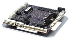
 Emerald-MM-8E/EL
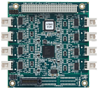
PCI/104-Express 4/8-Port Serial Port Module with Opto-isolation
The Emerald-MM-8EL-XT is a family of high performance PCIe/104 «OneBank» serial I/O modules offering 4 or 8 multiprotocol serial ports with software-controlled configuration and optional opto-isolation. An accessory microcontroller manages all port configuration and provides 8 auxiliary digital / analog I/O lines for general purpose use.
The serial ports are based on a high speed PCIe octal UART with 256-byte TX/RX FIFOs and auto RS-485 transmit control. Each serial port can be independently configured for RS-232, RS-422, or RS-485 protocols, along with programmable 120-ohm line termination. Each port is independently isolated with an isolated power + signal chip, plus additional isolators for control signals. The board features intelligent power management that limits inrush current on power-up and also enables power-down of unused serial ports for power savings.
Opto-isolated models feature independent 2500VRMS isolation circuits for enhanced reliability in vehicle or long cable applications. All ports also feature +/-15KV ESD protection. Each serial port is available on an independent latching connector for increased isolation and ruggedness. With its wide operating temperature range and high resistance to shock and vibration, the EMM-8EL-XT fits a wide variety of rugged and on-vehicle embedded serial I/O application needs.
EMM-8EL-XT also offers 8 digital/analog I/O lines which are programmable from the on-board microcontroller. Each I/O line can be configured for digital input or output. Seven of the I/O lines can be configured for 12-bit A/D input with selectable 0-2.048V or 0-3.3V input ranges.
EMM-8EL-XT contains no configuration jumpers; all configuration and control is done with an onboard microcontroller using application software included with the product. All configuration settings are stored in the microcontroller’s flash memory and are automatically loaded on power-up.
Cable Kits
Cable kits are available for both 4-port and 8-port boards They include individual cables with dB9 male connectors for each serial port and a ribbon cable for the auxiliary analog/digital I/O.
Configuration software
The EMM-8E family includes an on-board microcontroller to handle all configuration and control of the board’s features. The microcontroller is managed with a comprehensive software suite that makes configuring the EMM-8E fast and simple. A graphical control panel, a console application, and drivers for Windows and Linux are provided to enable convenient configuration of the board and control of the I/O features in a laboratory or system assembly environment, or embedded in the customer’s application software.
Emerald-MM-8E/EL
PCI/104-Express 4/8-Port Serial Port Module with Opto-isolation
The Emerald-MM-8EL-XT is a family of high performance PCIe/104 «OneBank» serial I/O modules offering 4 or 8 multiprotocol serial ports with software-controlled configuration and optional opto-isolation. An accessory microcontroller manages all port configuration and provides 8 auxiliary digital / analog I/O lines for general purpose use.
The serial ports are based on a high speed PCIe octal UART with 256-byte TX/RX FIFOs and auto RS-485 transmit control. Each serial port can be independently configured for RS-232, RS-422, or RS-485 protocols, along with programmable 120-ohm line termination. Each port is independently isolated with an isolated power + signal chip, plus additional isolators for control signals. The board features intelligent power management that limits inrush current on power-up and also enables power-down of unused serial ports for power savings.
Opto-isolated models feature independent 2500VRMS isolation circuits for enhanced reliability in vehicle or long cable applications. All ports also feature +/-15KV ESD protection. Each serial port is available on an independent latching connector for increased isolation and ruggedness. With its wide operating temperature range and high resistance to shock and vibration, the EMM-8EL-XT fits a wide variety of rugged and on-vehicle embedded serial I/O application needs.
EMM-8EL-XT also offers 8 digital/analog I/O lines which are programmable from the on-board microcontroller. Each I/O line can be configured for digital input or output. Seven of the I/O lines can be configured for 12-bit A/D input with selectable 0-2.048V or 0-3.3V input ranges.
EMM-8EL-XT contains no configuration jumpers; all configuration and control is done with an onboard microcontroller using application software included with the product. All configuration settings are stored in the microcontroller’s flash memory and are automatically loaded on power-up.
Cable Kits
Cable kits are available for both 4-port and 8-port boards They include individual cables with dB9 male connectors for each serial port and a ribbon cable for the auxiliary analog/digital I/O.
Configuration software
The EMM-8E family includes an on-board microcontroller to handle all configuration and control of the board’s features. The microcontroller is managed with a comprehensive software suite that makes configuring the EMM-8E fast and simple. A graphical control panel, a console application, and drivers for Windows and Linux are provided to enable convenient configuration of the board and control of the I/O features in a laboratory or system assembly environment, or embedded in the customer’s application software.
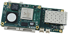
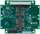 E104-MPE
PCI/104-Express Quad PCIe MiniCard Carrier
The PCIe MiniCard carrier provides up to four PCIe MiniCard sockets on a PCI/104-Express form factor board. All four sockets have PCIe x 1 and USB interfaces and support full size and half size PCIe MiniCard modules.
The module provides full support to all sockets while consuming only a single lane of host SBC resources. SIM card support is provided for two sockets.
All power is derived from the PCIe/104 connector 5V power tab. The PCI-104 connector provides a pass through connection and is not used by the module.
Extended temperature capability (-40°C to +85°C) enables the board to operate in environments with extreme temperature swings, such as vehicles or outdoor installations. For further enhanced ruggedness, zero ohm resistors can replace jumpers.
E104-MPE
PCI/104-Express Quad PCIe MiniCard Carrier
The PCIe MiniCard carrier provides up to four PCIe MiniCard sockets on a PCI/104-Express form factor board. All four sockets have PCIe x 1 and USB interfaces and support full size and half size PCIe MiniCard modules.
The module provides full support to all sockets while consuming only a single lane of host SBC resources. SIM card support is provided for two sockets.
All power is derived from the PCIe/104 connector 5V power tab. The PCI-104 connector provides a pass through connection and is not used by the module.
Extended temperature capability (-40°C to +85°C) enables the board to operate in environments with extreme temperature swings, such as vehicles or outdoor installations. For further enhanced ruggedness, zero ohm resistors can replace jumpers.
 EPS-12002L
Compact 12+2 Port Managed Ethernet Switch
Main features:
Rugged Ethernet switch for vehicle and other harsh environment applications
12 gigabit Ethernet ports for twisted pair connections
2 1/2.5/5/10G SFP+ sockets for fiber or copper transceivers
All ports feature non-blocking wire-speed performance
Layer 2+ switching and Layer 3 routing software available
IEEE 1588 PTP support available
Software customization and branding available
Rugged design with latching connectors
-40 to +85°C operating temperature
5.3×2.2″ / 136×55mm
Heat sink and heat spreader thermal options
The EPS-12002L is a compact managed rugged Ethernet switch based on Diamond’s EPSM-10GX Ethernet switch module. The switch consists of the EPSM-10GX module mounted on a carrier board that provides power, magnetics, and connectors, along with a heat sink or heat spreader.
EPS-12002L provides 12x 10/100/1000Mbps copper ports and 2x 1/2.5/5/10Gbps SFP+ sockets for fiber or copper transceivers. EPS-12002L is ideal for vehicle and industrial applications requiring a small form factor with gigabit Ethernet switching and fiber connectivity support.
Two software packages are available, Layer 2+ switching and Layer 3 routing/switching. All software features are manageable via a GUI web interface accessible over any port, as well as with a command language accessed via a built-in RS-232 port.
EPS-12002L is designed specifically to meet the challenges of vehicle and other rugged environments, with its −40/+85°C operating temperature range, latching I/O connectors, and MIL-STD-202G shock/vibration resistance. A 5-36V input power supply provides compatibility with a range of industrial and vehicle power supplies.
Embedded Software
Two software packages are available: Layer 2+ switching and Layer 3 routing/switching. In addition, IEEE-1588 precision time protocol support is available with a minor modification to install a precision clock circuit on the board. All software features are manageable via a GUI web interface accessible over any port, as well as with a command language accessed via a built-in RS-232 port. Customer branding is available to put your logo / color scheme / part numbers on the GUI and serial interface.
The table below shows some of the more popular features available.
Layer 2+ software highlights include the following:
8K MAC addresses and 4K VLANs (IEEE 802.1Q)
8K IPv4 and IPv6 multicast group support
Jumbo frame support at all speeds
Flexible link aggregation support based on Layer-2 through Layer-4 information (IEEE 802.3ad)
Multicast and broadcast storm control, as well as flooding control
Rapid Spanning Tree protocol (RSTP) and MSTP
Multiple protocol support: IEEE 802.1d, IEEE 802.1w, IEEE 802.1s, and IEEE 802.1X
8 priorities and 8 QoS queues per port with scheduling
Layer3 software additional highlights:
Hardware- and software-based IPv6 L3 static routing
RFC 2328 OSPFv2 dynamic routing
IEEE 1588 precision time protocol (PTP)
RADIUS accounting
Port and Queue policers
Cable Kit
Cable Kit for EPS-12000-CM: 3x Quad Gigabit Ethernet cables, Power cable, Serial cable.
EPS-12002L
Compact 12+2 Port Managed Ethernet Switch
Main features:
Rugged Ethernet switch for vehicle and other harsh environment applications
12 gigabit Ethernet ports for twisted pair connections
2 1/2.5/5/10G SFP+ sockets for fiber or copper transceivers
All ports feature non-blocking wire-speed performance
Layer 2+ switching and Layer 3 routing software available
IEEE 1588 PTP support available
Software customization and branding available
Rugged design with latching connectors
-40 to +85°C operating temperature
5.3×2.2″ / 136×55mm
Heat sink and heat spreader thermal options
The EPS-12002L is a compact managed rugged Ethernet switch based on Diamond’s EPSM-10GX Ethernet switch module. The switch consists of the EPSM-10GX module mounted on a carrier board that provides power, magnetics, and connectors, along with a heat sink or heat spreader.
EPS-12002L provides 12x 10/100/1000Mbps copper ports and 2x 1/2.5/5/10Gbps SFP+ sockets for fiber or copper transceivers. EPS-12002L is ideal for vehicle and industrial applications requiring a small form factor with gigabit Ethernet switching and fiber connectivity support.
Two software packages are available, Layer 2+ switching and Layer 3 routing/switching. All software features are manageable via a GUI web interface accessible over any port, as well as with a command language accessed via a built-in RS-232 port.
EPS-12002L is designed specifically to meet the challenges of vehicle and other rugged environments, with its −40/+85°C operating temperature range, latching I/O connectors, and MIL-STD-202G shock/vibration resistance. A 5-36V input power supply provides compatibility with a range of industrial and vehicle power supplies.
Embedded Software
Two software packages are available: Layer 2+ switching and Layer 3 routing/switching. In addition, IEEE-1588 precision time protocol support is available with a minor modification to install a precision clock circuit on the board. All software features are manageable via a GUI web interface accessible over any port, as well as with a command language accessed via a built-in RS-232 port. Customer branding is available to put your logo / color scheme / part numbers on the GUI and serial interface.
The table below shows some of the more popular features available.
Layer 2+ software highlights include the following:
8K MAC addresses and 4K VLANs (IEEE 802.1Q)
8K IPv4 and IPv6 multicast group support
Jumbo frame support at all speeds
Flexible link aggregation support based on Layer-2 through Layer-4 information (IEEE 802.3ad)
Multicast and broadcast storm control, as well as flooding control
Rapid Spanning Tree protocol (RSTP) and MSTP
Multiple protocol support: IEEE 802.1d, IEEE 802.1w, IEEE 802.1s, and IEEE 802.1X
8 priorities and 8 QoS queues per port with scheduling
Layer3 software additional highlights:
Hardware- and software-based IPv6 L3 static routing
RFC 2328 OSPFv2 dynamic routing
IEEE 1588 precision time protocol (PTP)
RADIUS accounting
Port and Queue policers
Cable Kit
Cable Kit for EPS-12000-CM: 3x Quad Gigabit Ethernet cables, Power cable, Serial cable.
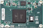 EPSM-12G2F
26-Port Miniature Rugged Managed Ethernet Switch Module
EPSM-12G2F is a managed Ethernet switch module in an ultra-compact 2.2″ x 3.3″ (55×84mm) size offering 24x 10/100/1000Mbps copper ports and 2x 1-2.5Gbps SFP ports. It supports an embedded software package offering a full suite of Layer 2 managed Ethernet switching capabilities.
The module is intended to be used on a carrier board to implement a complete Ethernet switching solution. The core Ethernet switching technology is almost fully encapsulated on the module; for many applications, only the «last inch» of magnetics and I/O connectors is required to complete the circuit, enabling easy development of custom form factor compact, rugged Ethernet switch solutions.
EPSM-12G2F offers compelling advantages over in-house designed Ethernet switches requiring mid-range software features:
Small size fits into robots, drones, and other applications where size and weight are critical
Rugged design and wide temperature capability are ideal for vehicle applications where high levels of shock and vibration are present
Off the shelf solution significantly reduces development time and risk
Built-in embedded software provides the most popular managed switch features, all configurable via web or serial port interfaces, eliminating the need for any software development
Embedded Software
EPSM-12G2F includes the feature-rich WebStaX Layer 2 managed Ethernet switch software. The table below shows some of the more popular features included:
8K MAC addresses and 4K VLANs (IEEE 802.1Q)
8K IPv4 and IPv6 multicast group support
Jumbo frame support at all speeds
Flexible link aggregation support based on Layer-2 through Layer-4 information (IEEE 802.3ad)
Multicast and broadcast storm control, as well as flooding control
Rapid Spanning Tree protocol (RSTP) and MSTP
Multiple protocol support: IEEE 802.1d, IEEE 802.1w, IEEE 802.1s, and IEEE 802.1X
8 priorities and 8 QoS queues per port with scheduling
Cooling Options
Two cooling accessory options are available: A heat sink provides convection cooling in a low profile, while a heat spreader provides improved conduction cooling for superior high temperature performance in applications where physical contact with the system enclosure is available.
Development Support
A design guide is available with circuit details and other technical information necessary to design a carrier board around the EPSM-12G2F. A development kit is also available including:
A technical design package (schematics, PCB layout, and Bill of Materials) of the EPS-24G4X carrier board, featuring support for 12 1G ports from the module, PHY for 12 additional 1G ports, dual SFP sockets, LED control logic, and power supply circuit
CPLD code for status LED control logic
A complete EPS-24G4X switch with the EPSM-12G2F module installed
A cable kit
Free custom branding of the embedded software (logo / color / title only; custom configurations are extra charge)
EPSM-12G2F
26-Port Miniature Rugged Managed Ethernet Switch Module
EPSM-12G2F is a managed Ethernet switch module in an ultra-compact 2.2″ x 3.3″ (55×84mm) size offering 24x 10/100/1000Mbps copper ports and 2x 1-2.5Gbps SFP ports. It supports an embedded software package offering a full suite of Layer 2 managed Ethernet switching capabilities.
The module is intended to be used on a carrier board to implement a complete Ethernet switching solution. The core Ethernet switching technology is almost fully encapsulated on the module; for many applications, only the «last inch» of magnetics and I/O connectors is required to complete the circuit, enabling easy development of custom form factor compact, rugged Ethernet switch solutions.
EPSM-12G2F offers compelling advantages over in-house designed Ethernet switches requiring mid-range software features:
Small size fits into robots, drones, and other applications where size and weight are critical
Rugged design and wide temperature capability are ideal for vehicle applications where high levels of shock and vibration are present
Off the shelf solution significantly reduces development time and risk
Built-in embedded software provides the most popular managed switch features, all configurable via web or serial port interfaces, eliminating the need for any software development
Embedded Software
EPSM-12G2F includes the feature-rich WebStaX Layer 2 managed Ethernet switch software. The table below shows some of the more popular features included:
8K MAC addresses and 4K VLANs (IEEE 802.1Q)
8K IPv4 and IPv6 multicast group support
Jumbo frame support at all speeds
Flexible link aggregation support based on Layer-2 through Layer-4 information (IEEE 802.3ad)
Multicast and broadcast storm control, as well as flooding control
Rapid Spanning Tree protocol (RSTP) and MSTP
Multiple protocol support: IEEE 802.1d, IEEE 802.1w, IEEE 802.1s, and IEEE 802.1X
8 priorities and 8 QoS queues per port with scheduling
Cooling Options
Two cooling accessory options are available: A heat sink provides convection cooling in a low profile, while a heat spreader provides improved conduction cooling for superior high temperature performance in applications where physical contact with the system enclosure is available.
Development Support
A design guide is available with circuit details and other technical information necessary to design a carrier board around the EPSM-12G2F. A development kit is also available including:
A technical design package (schematics, PCB layout, and Bill of Materials) of the EPS-24G4X carrier board, featuring support for 12 1G ports from the module, PHY for 12 additional 1G ports, dual SFP sockets, LED control logic, and power supply circuit
CPLD code for status LED control logic
A complete EPS-24G4X switch with the EPSM-12G2F module installed
A cable kit
Free custom branding of the embedded software (logo / color / title only; custom configurations are extra charge)
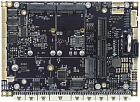 Jasper
Rugged COM Express Type 6 Carrier Board and SBC with Rich I/O and Expansion
Jasper is a COM Express carrier board and SBC for Type 6 Basic (125×95mm) and Compact (95×95mm) modules. It is designed for applications that require ruggedness, a high level of I/O, or extended product lifetime.
Notable features of Jasper include:
Rugged mechanical design with thicker PCB and latching connectors
Wide temperature operation — up to −40 to +85C (depending on the installed COM)
Built-in 16-bit data acquisition circuit with autocalibration
Dual minicard sockets with PCIe and USB interfaces
Dual M.2 sockets for flash memory and network connectivity
PCIe/104 expansion socket supporting x16 and x1 links
Jasper is available as a carrier board alone, for user integration with a COM of your choice, or as a ready to run «single-board computer» with an 11th generation Intel Xeon/Core i7 processor COM installed. Both Windows and Linux OS support are standard, while other OS support is available upon request.
Flexible Design to Fit Any Application
The most popular I/O on Jasper is provided on a single row of connectors along the front edge of the PCB. This arrangement supports dual connection modes. First Jasper can be used with traditional cables, with each cable providing a positive locking feature for increased shock and vibration resistance. Secondly the single row of connectors makes it easy to design and build I/O connector boards that match the end application’s exact requirements. For example a connector board with commercial connectors (RJ-45, USB type A, etc.) or MIL-DTL-38999 rugged circuit connectors can be plugged directly into the Jasper I/O connectors to create a «cable-free» solution. Such a connector board can dramatically reduce assembly time and cost for the end system.
Rugged design
Jasper was designed from the ground up with a comprehensive set of features to meet the challenges of rugged environments and applications:
The 50% thicker PCB increases rigidity and improves reliability of fine pitch and high-ball-count BGA solder joints
Almost all I/O connectors are positive latching (not friction lock) for increased ruggedness
A bottom-side heat spreader provides more efficient cooling than a traditional heat sink
All components are rated and/or tested to ensure reliable −40 to +85 o C operation
Thermal Dissipation
Jasper supports installation of the COM and its heat spreader on the bottom side of the carrier. This enables more efficient mounting and heat dissipation, since the COM’s heat is directly coupled to the enclosure body instead of relying on a top-side heat sink to dissipate heat into the air inside. Jasper’s mounting plate surrounds the COM heat spreader to provide mounting stability for the entire board assembly.
I/O Expansion
Jasper includes dual PCIe minicard sockets with both PCIe and USB interfaces, supporting a wide range of I/O and communications/networking modules from Diamond as well as third party vendors. It includes an M.2 E key socket for installation of wifi and other networking modules. The PCIe/104 socket enables use with PCIe/104 Type 1 I/O modules using x1, x4, x8, and x16 PCIe links (depending on the capability of the installed COM) as well as PCIe/104 OneBank modules using the x1 lanes on the first connector bank.
Cable Kit
The Jasper cable kit includes cables for all I/O and features on the board. All cables except for SATA have positive latching feature for resistance to shock and vibration.
Jasper
Rugged COM Express Type 6 Carrier Board and SBC with Rich I/O and Expansion
Jasper is a COM Express carrier board and SBC for Type 6 Basic (125×95mm) and Compact (95×95mm) modules. It is designed for applications that require ruggedness, a high level of I/O, or extended product lifetime.
Notable features of Jasper include:
Rugged mechanical design with thicker PCB and latching connectors
Wide temperature operation — up to −40 to +85C (depending on the installed COM)
Built-in 16-bit data acquisition circuit with autocalibration
Dual minicard sockets with PCIe and USB interfaces
Dual M.2 sockets for flash memory and network connectivity
PCIe/104 expansion socket supporting x16 and x1 links
Jasper is available as a carrier board alone, for user integration with a COM of your choice, or as a ready to run «single-board computer» with an 11th generation Intel Xeon/Core i7 processor COM installed. Both Windows and Linux OS support are standard, while other OS support is available upon request.
Flexible Design to Fit Any Application
The most popular I/O on Jasper is provided on a single row of connectors along the front edge of the PCB. This arrangement supports dual connection modes. First Jasper can be used with traditional cables, with each cable providing a positive locking feature for increased shock and vibration resistance. Secondly the single row of connectors makes it easy to design and build I/O connector boards that match the end application’s exact requirements. For example a connector board with commercial connectors (RJ-45, USB type A, etc.) or MIL-DTL-38999 rugged circuit connectors can be plugged directly into the Jasper I/O connectors to create a «cable-free» solution. Such a connector board can dramatically reduce assembly time and cost for the end system.
Rugged design
Jasper was designed from the ground up with a comprehensive set of features to meet the challenges of rugged environments and applications:
The 50% thicker PCB increases rigidity and improves reliability of fine pitch and high-ball-count BGA solder joints
Almost all I/O connectors are positive latching (not friction lock) for increased ruggedness
A bottom-side heat spreader provides more efficient cooling than a traditional heat sink
All components are rated and/or tested to ensure reliable −40 to +85 o C operation
Thermal Dissipation
Jasper supports installation of the COM and its heat spreader on the bottom side of the carrier. This enables more efficient mounting and heat dissipation, since the COM’s heat is directly coupled to the enclosure body instead of relying on a top-side heat sink to dissipate heat into the air inside. Jasper’s mounting plate surrounds the COM heat spreader to provide mounting stability for the entire board assembly.
I/O Expansion
Jasper includes dual PCIe minicard sockets with both PCIe and USB interfaces, supporting a wide range of I/O and communications/networking modules from Diamond as well as third party vendors. It includes an M.2 E key socket for installation of wifi and other networking modules. The PCIe/104 socket enables use with PCIe/104 Type 1 I/O modules using x1, x4, x8, and x16 PCIe links (depending on the capability of the installed COM) as well as PCIe/104 OneBank modules using the x1 lanes on the first connector bank.
Cable Kit
The Jasper cable kit includes cables for all I/O and features on the board. All cables except for SATA have positive latching feature for resistance to shock and vibration.
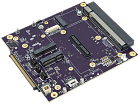 Osbourne
Carrier and Dev Kit for NVIDIA Jetson AGX Orin
Osbourne is a versatile carrier board for the NVIDIA Jetson AGX Orin high-performance GPU module. It provides access to all I/O features of the Orin module and includes numerous sockets for I/O expansion. Osbourne has been designed to be used in almost any application ranging from commercial to industrial to airborne to rugged military use.
Key highlights of Osbourne include:
Industry-standard camera adapter socket for use with a wide range of CSI, GMSL, and other cameras
10Gb Ethernet + 1GB Ethernet ports
Wide temperature operation — matching the range of the Orin module
Dual minicard sockets with PCIe and USB interfaces
Dual M.2 sockets for flash memory (M key 2242/2280) and network connectivity (E key 2230)
I/O concentrator connector enables use with standard and custom I/O breakout boards
Osbourne is available as a carrier board alone or with an Orin module and fan sink installed and ready for use. A Linux OS based on Nvidia L4T and customized to support all I/O on Osbourne is available for free download.
Flexible I/O Connector Design
All I/O on Osbourne is accessed through a single high-speed, high-density connector along the board edge. This decouples the board design from any specific I/O connector arrangement and frees you to select whatever I/O connector scheme you want. Standard connector boards are available for typical use cases, including a panel-mount connector board for installation in an enclosure and a breakout board for use with cables.
Panel I/O Board
The Panel I/O board provides the ability to install Osbourne directly into an enclosure without the use of cables. All I/O is provided on a series of commercial-style connectors designed to be mounted in an enclosure front panel. Panel I/O boards can also be designed with right-angle orientation.
I/O Expansion
Osbourne includes dual PCIe minicard sockets with both PCIe and USB interfaces, supporting a wide range of I/O and communications/networking modules from Diamond as well as third party vendors. It includes an M.2 E key socket for installation of WiFi and other networking modules.
Mass storage is provided with an M.2 2242/2280 NVME socket and a Micro-SD card socket.
Osbourne
Carrier and Dev Kit for NVIDIA Jetson AGX Orin
Osbourne is a versatile carrier board for the NVIDIA Jetson AGX Orin high-performance GPU module. It provides access to all I/O features of the Orin module and includes numerous sockets for I/O expansion. Osbourne has been designed to be used in almost any application ranging from commercial to industrial to airborne to rugged military use.
Key highlights of Osbourne include:
Industry-standard camera adapter socket for use with a wide range of CSI, GMSL, and other cameras
10Gb Ethernet + 1GB Ethernet ports
Wide temperature operation — matching the range of the Orin module
Dual minicard sockets with PCIe and USB interfaces
Dual M.2 sockets for flash memory (M key 2242/2280) and network connectivity (E key 2230)
I/O concentrator connector enables use with standard and custom I/O breakout boards
Osbourne is available as a carrier board alone or with an Orin module and fan sink installed and ready for use. A Linux OS based on Nvidia L4T and customized to support all I/O on Osbourne is available for free download.
Flexible I/O Connector Design
All I/O on Osbourne is accessed through a single high-speed, high-density connector along the board edge. This decouples the board design from any specific I/O connector arrangement and frees you to select whatever I/O connector scheme you want. Standard connector boards are available for typical use cases, including a panel-mount connector board for installation in an enclosure and a breakout board for use with cables.
Panel I/O Board
The Panel I/O board provides the ability to install Osbourne directly into an enclosure without the use of cables. All I/O is provided on a series of commercial-style connectors designed to be mounted in an enclosure front panel. Panel I/O boards can also be designed with right-angle orientation.
I/O Expansion
Osbourne includes dual PCIe minicard sockets with both PCIe and USB interfaces, supporting a wide range of I/O and communications/networking modules from Diamond as well as third party vendors. It includes an M.2 E key socket for installation of WiFi and other networking modules.
Mass storage is provided with an M.2 2242/2280 NVME socket and a Micro-SD card socket.
 Saturn
Rugged Apollo Lake x7-E3950 SBC with Data Acquisition and PCIe/104 Expansion
Saturn combines a feature-rich Atom‑class processor‑based SBC with a professional-quality industrial analog and digital data acquisition subsystem and flexible I/O expansion in a single board designed for rugged applications.
Intel "Apollo Lake" x7-E3950 1.6GHz (burstable 2.0GHz) quad-core processor with 15-year lifecycle
4GB non-ECC or 8GB ECC RAM soldered down
Integrated professional-quality analog and digital data acquisition subsystem with software support
Bottom side heat spreader with integrated thermal pad provides efficient cooling and convenient mounting
Full −40 to +85ºC industrial operating temperature range
Thicker PCB and latching connectors increase resistance to shock and vibration
PCIe/104 OneBank expansion socket for industry-standard rugged I/O expansion
Minicard expansion socket for versatile low-cost I/O
Saturn was designed from the ground up with a comprehensive set of features to meet the challenges of rugged environments and applications:
Memory is soldered down to avoid problems that can occur with commercial style SODIMM type memory modules
The 50% thicker PCB increases rigidity and improves reliability of fine pitch and high-ball-count BGA solder joints
All I/O connectors are latching for increased ruggedness
A bottom-side heat spreader provides more efficient cooling than a traditional heat sink. Processor and memory chips are both thermally connected to the heat spreader. In addition the exterior surface features recessed thermal pads for improved thermal connectivity to the system enclosure.
All components are rated and/or tested to ensure reliable −40 to +85ºC operation
Integrated Data Acquisition
Saturn is a member of Diamond’s 2-in-1 series of SBCs with integrated data acquisition. For applications requiring precision analog I/O, a 2-in-1 SBC is an ideal choice because it reduces the number of boards in the system, resulting in a system that is smaller, lighter, lower cost, and easier to assemble and maintain. The features of the Saturn DAQ circuit surpass those found on most other embedded SBCs in both variety and quality, providing a comprehensive, professional quality subsystem backed with top of the line software support. «A» models include the full DAQ circuit with both analog and digital I/O features, while «D» models include only the digital I/O features.
Saturn’s data acquisition circuit features autocalibration, which maintains best accuracy of the A/D and D/A circuits regardless of time and temperature swings. Using the supplied Universal Driver software library, the circuit can be quickly calibrated to within +/-2LSB accuracy at any time, relative to the on-board precision reference voltage circuit.
The A/D circuit includes 16 single-ended / 8 differential analog input channels with programmable input ranges and a maximum aggregate sampling rate of 250KHz. A built-in programmable counter/timer supports accurate high-speed sampling with precise timing. The 2048-sample FIFO with programmable threshold ensures error-free sampling and enables you to tune the performance of the circuit to minimize interrupt processing overhead.
The D/A circuit consists of 4 16-bit D/A voltage outputs with independently programmable output ranges including 0-10V, +/-10V, 0-5V, and +/-5V. A 2048-sample waveform buffer is included to support arbitrary waveform generator functions on up to 4 channels simultaneously.
The digital I/O circuit consists of GPIO, counter/timers, and pulse-width modulators. The GPIO circuit provides 22 buffered digital I/O lines, consisting of one 8-bit port and 14 1-bit ports. Each port is individually programmable for input or output. The 1-bit direction controllable ports provide better matching of input and output quantities to each application. Jumper configuration enables selection of 5V/3.3V logic levels and pull-up or pull-down resistors on the digital I/O lines.
The 8 32-bit programmable counter/timers feature both up and down counting with clocking selectable from an external digital signal or the on-board 50MHz clock. Counters can be used for generating programmable output frequencies with programmable output pulse widths, counting external events, generating interrupts to the host processor at a programmable rate, and driving A/D sampling at precise frequencies with perfect timing between samples.
The circuit further includes 4 24-bit programmable pulse width modulators also driven by the on-board 50MHz clock. These feature programmable rate, duty cycle, and polarity, with real-time rate and duty cycle update capability.
Software Support
Diamond Systems’ Universal Driver software provides unmatched power and flexibility for embedded data acquisition programming with PC/104 and small form factor I/O boards. It provides flexible C-language programming support for Windows and Linux to control all data acquisition features on Saturn, as well as Diamond’s MiniCard data acquisition modules that can be used with Saturn.
A powerful and convenient graphical control panel provides instant, easy access to all data acquisition features on the board. It can be used for proof of concept, testing, and even system debugging.
I/O expansion
Saturn provides two sockets for the installation of I/O expansion modules:
A PCIe/104 OneBank I/O expansion socket provides 4 PCIe x1 lanes and 2 USB 2.0 ports to interface with hundreds of PCIe/104 I/O modules from vendors around the world. Only top side expansion is supported, since the bottom side of Saturn is covered by the heat spreader.
A full-size PCIe MiniCard socket supports both PCIe and USB minicards. Saturn supports Diamond’s complete line of PCIe MiniCards.
What is PCIe/104 OneBank™?
OneBank™ is the name given to the PCIe/104 standard that utilizes a more compact, cost effective connector to support rugged, high-speed I/O expansion. The original PCIe/104 connector features 3 «banks» of contacts. The 2nd and 3rd banks contain PCIe x8 / x16 signals that are not supported on Atom processors nor used by most I/O expansion modules. By eliminating these signals, a smaller and more cost effective connector can be used to provide compatibility with any PCIe/104 I/O module that uses a PCIe x1 or USB host connection, while freeing up precious PCB space for additional I/O or connectors. OneBank is an official expansion connector supported by the PC/104 Consortium (of which Diamond Systems was a founding member).
Mass storage
Saturn offers two options for mass storage:
An M.2 2242 size SATA socket is provided for onboard mass storage. Modules up to 1TB are available. This is the most common choice.
A standard 7-pin SATA connector is available for connecting a standard 2.5″ or other form factor hard drive. This connector can be used when higher capacity storage is needed. Diamond offers accessory board ACC-HDDMOUNT which allows a 2.5″ drive to be mounted on the PC/104 holes on Saturn.
Cable Kit
The Saturn cable kit includes all I/O cables needed for all I/O connectors on Saturn except the LCD data and backlight cables, which are customized for each individual application. Cables are normally sold as complete kits. Individual cables may be available in some cases or may be ordered with minimum order quantities; contact us for availability. Detailed drawings listing all components are provided to enable customers to build their own cables.
Development kits
Development kits are available to support quick project startup. Each kit includes the Saturn SBC, a cable kit, and a programmed 64GB flashdisk with a read-to-run installation of Windows 10 or Linux operating system, plus a backup USB memory device. Simply install the flashdisk, attach the cables, add your keyboard, mouse, and display, and connect power, and the board will boot into a fully functional OS.
Configuration files and instructions are provided to rebuild the OS with your application. The Linux kit includes all the tools needed to rebuild the OS. The Windows 10 kit includes a runtime license.
A software-only kit is available that consists of just the programmed flashdisk and backup USB memory device. This software kit is intended for customers who already have one or more Saturn SBCs. One software kit can be used on any number of Saturn boards. (Windows licensing requirements still apply.)
Saturn
Rugged Apollo Lake x7-E3950 SBC with Data Acquisition and PCIe/104 Expansion
Saturn combines a feature-rich Atom‑class processor‑based SBC with a professional-quality industrial analog and digital data acquisition subsystem and flexible I/O expansion in a single board designed for rugged applications.
Intel "Apollo Lake" x7-E3950 1.6GHz (burstable 2.0GHz) quad-core processor with 15-year lifecycle
4GB non-ECC or 8GB ECC RAM soldered down
Integrated professional-quality analog and digital data acquisition subsystem with software support
Bottom side heat spreader with integrated thermal pad provides efficient cooling and convenient mounting
Full −40 to +85ºC industrial operating temperature range
Thicker PCB and latching connectors increase resistance to shock and vibration
PCIe/104 OneBank expansion socket for industry-standard rugged I/O expansion
Minicard expansion socket for versatile low-cost I/O
Saturn was designed from the ground up with a comprehensive set of features to meet the challenges of rugged environments and applications:
Memory is soldered down to avoid problems that can occur with commercial style SODIMM type memory modules
The 50% thicker PCB increases rigidity and improves reliability of fine pitch and high-ball-count BGA solder joints
All I/O connectors are latching for increased ruggedness
A bottom-side heat spreader provides more efficient cooling than a traditional heat sink. Processor and memory chips are both thermally connected to the heat spreader. In addition the exterior surface features recessed thermal pads for improved thermal connectivity to the system enclosure.
All components are rated and/or tested to ensure reliable −40 to +85ºC operation
Integrated Data Acquisition
Saturn is a member of Diamond’s 2-in-1 series of SBCs with integrated data acquisition. For applications requiring precision analog I/O, a 2-in-1 SBC is an ideal choice because it reduces the number of boards in the system, resulting in a system that is smaller, lighter, lower cost, and easier to assemble and maintain. The features of the Saturn DAQ circuit surpass those found on most other embedded SBCs in both variety and quality, providing a comprehensive, professional quality subsystem backed with top of the line software support. «A» models include the full DAQ circuit with both analog and digital I/O features, while «D» models include only the digital I/O features.
Saturn’s data acquisition circuit features autocalibration, which maintains best accuracy of the A/D and D/A circuits regardless of time and temperature swings. Using the supplied Universal Driver software library, the circuit can be quickly calibrated to within +/-2LSB accuracy at any time, relative to the on-board precision reference voltage circuit.
The A/D circuit includes 16 single-ended / 8 differential analog input channels with programmable input ranges and a maximum aggregate sampling rate of 250KHz. A built-in programmable counter/timer supports accurate high-speed sampling with precise timing. The 2048-sample FIFO with programmable threshold ensures error-free sampling and enables you to tune the performance of the circuit to minimize interrupt processing overhead.
The D/A circuit consists of 4 16-bit D/A voltage outputs with independently programmable output ranges including 0-10V, +/-10V, 0-5V, and +/-5V. A 2048-sample waveform buffer is included to support arbitrary waveform generator functions on up to 4 channels simultaneously.
The digital I/O circuit consists of GPIO, counter/timers, and pulse-width modulators. The GPIO circuit provides 22 buffered digital I/O lines, consisting of one 8-bit port and 14 1-bit ports. Each port is individually programmable for input or output. The 1-bit direction controllable ports provide better matching of input and output quantities to each application. Jumper configuration enables selection of 5V/3.3V logic levels and pull-up or pull-down resistors on the digital I/O lines.
The 8 32-bit programmable counter/timers feature both up and down counting with clocking selectable from an external digital signal or the on-board 50MHz clock. Counters can be used for generating programmable output frequencies with programmable output pulse widths, counting external events, generating interrupts to the host processor at a programmable rate, and driving A/D sampling at precise frequencies with perfect timing between samples.
The circuit further includes 4 24-bit programmable pulse width modulators also driven by the on-board 50MHz clock. These feature programmable rate, duty cycle, and polarity, with real-time rate and duty cycle update capability.
Software Support
Diamond Systems’ Universal Driver software provides unmatched power and flexibility for embedded data acquisition programming with PC/104 and small form factor I/O boards. It provides flexible C-language programming support for Windows and Linux to control all data acquisition features on Saturn, as well as Diamond’s MiniCard data acquisition modules that can be used with Saturn.
A powerful and convenient graphical control panel provides instant, easy access to all data acquisition features on the board. It can be used for proof of concept, testing, and even system debugging.
I/O expansion
Saturn provides two sockets for the installation of I/O expansion modules:
A PCIe/104 OneBank I/O expansion socket provides 4 PCIe x1 lanes and 2 USB 2.0 ports to interface with hundreds of PCIe/104 I/O modules from vendors around the world. Only top side expansion is supported, since the bottom side of Saturn is covered by the heat spreader.
A full-size PCIe MiniCard socket supports both PCIe and USB minicards. Saturn supports Diamond’s complete line of PCIe MiniCards.
What is PCIe/104 OneBank™?
OneBank™ is the name given to the PCIe/104 standard that utilizes a more compact, cost effective connector to support rugged, high-speed I/O expansion. The original PCIe/104 connector features 3 «banks» of contacts. The 2nd and 3rd banks contain PCIe x8 / x16 signals that are not supported on Atom processors nor used by most I/O expansion modules. By eliminating these signals, a smaller and more cost effective connector can be used to provide compatibility with any PCIe/104 I/O module that uses a PCIe x1 or USB host connection, while freeing up precious PCB space for additional I/O or connectors. OneBank is an official expansion connector supported by the PC/104 Consortium (of which Diamond Systems was a founding member).
Mass storage
Saturn offers two options for mass storage:
An M.2 2242 size SATA socket is provided for onboard mass storage. Modules up to 1TB are available. This is the most common choice.
A standard 7-pin SATA connector is available for connecting a standard 2.5″ or other form factor hard drive. This connector can be used when higher capacity storage is needed. Diamond offers accessory board ACC-HDDMOUNT which allows a 2.5″ drive to be mounted on the PC/104 holes on Saturn.
Cable Kit
The Saturn cable kit includes all I/O cables needed for all I/O connectors on Saturn except the LCD data and backlight cables, which are customized for each individual application. Cables are normally sold as complete kits. Individual cables may be available in some cases or may be ordered with minimum order quantities; contact us for availability. Detailed drawings listing all components are provided to enable customers to build their own cables.
Development kits
Development kits are available to support quick project startup. Each kit includes the Saturn SBC, a cable kit, and a programmed 64GB flashdisk with a read-to-run installation of Windows 10 or Linux operating system, plus a backup USB memory device. Simply install the flashdisk, attach the cables, add your keyboard, mouse, and display, and connect power, and the board will boot into a fully functional OS.
Configuration files and instructions are provided to rebuild the OS with your application. The Linux kit includes all the tools needed to rebuild the OS. The Windows 10 kit includes a runtime license.
A software-only kit is available that consists of just the programmed flashdisk and backup USB memory device. This software kit is intended for customers who already have one or more Saturn SBCs. One software kit can be used on any number of Saturn boards. (Windows licensing requirements still apply.)
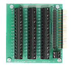 STB-104 Module
STB-104: PC/104 Screw Terminal Board
The STB-PC/104 is a miniature PC/104-format screw‑terminal board that enables you to easily connect sensors, control signals, etc. to a PC/104 system. A 50-pin connector is provided for mating with a short cable to any Diamond Systems data acquisition module. Each pin on the connector is brought out to a screw terminal, enabling you to easily add, remove, and modify wiring as needed without complicated cable construction and modifications. The screw terminals are angled for easy operation.
This unique board is the same size as a PC/104 module, so it fits conveniently right on top of the PC/104 stack. All necessary mounting hardware is included.
Dimensions: 3.55″ x 3.775″
Screw terminal height: 0.59″ above top of PCB
Configuration: 3 rows of 16 terminals + 1 row of 2 terminals
STB-104 Module
STB-104: PC/104 Screw Terminal Board
The STB-PC/104 is a miniature PC/104-format screw‑terminal board that enables you to easily connect sensors, control signals, etc. to a PC/104 system. A 50-pin connector is provided for mating with a short cable to any Diamond Systems data acquisition module. Each pin on the connector is brought out to a screw terminal, enabling you to easily add, remove, and modify wiring as needed without complicated cable construction and modifications. The screw terminals are angled for easy operation.
This unique board is the same size as a PC/104 module, so it fits conveniently right on top of the PC/104 stack. All necessary mounting hardware is included.
Dimensions: 3.55″ x 3.775″
Screw terminal height: 0.59″ above top of PCB
Configuration: 3 rows of 16 terminals + 1 row of 2 terminals
